PROCEDURE 4 | SEAT |
|
|
FRONT SEAT HEIGHT ADJUSTMENT
NOTE: This procedure is for
WARNING
The position of the footrest, camber tube, seat height, the tautness of the back upholstery, as well as the user's condition are directly related to the chair's stabil- ity. Any change to one (1) or any combination of the five (5) may cause the chair to decrease in stability. Use EXTREME caution when using a new seating position.
SEAT
Before 2001 (FIGURE 4)
1.Loosen, but do not remove the two (2) set screws that secure the seat rail to the chair frame.
2.Loosen, but do not remove the four (4) set screws that secure the seat adjust- ment weldment in place.
3.Move the seat up or down until the seat is at the desired height.
4.Securely tighten the four (4) set screws that secure the seat adjustment weldment in place.
5.Securely tighten the two (2) set screws that secure the seat rail to the chair frame.
6.Adjust the footrest height. Refer to PRO- CEDURE 7 of this manual.
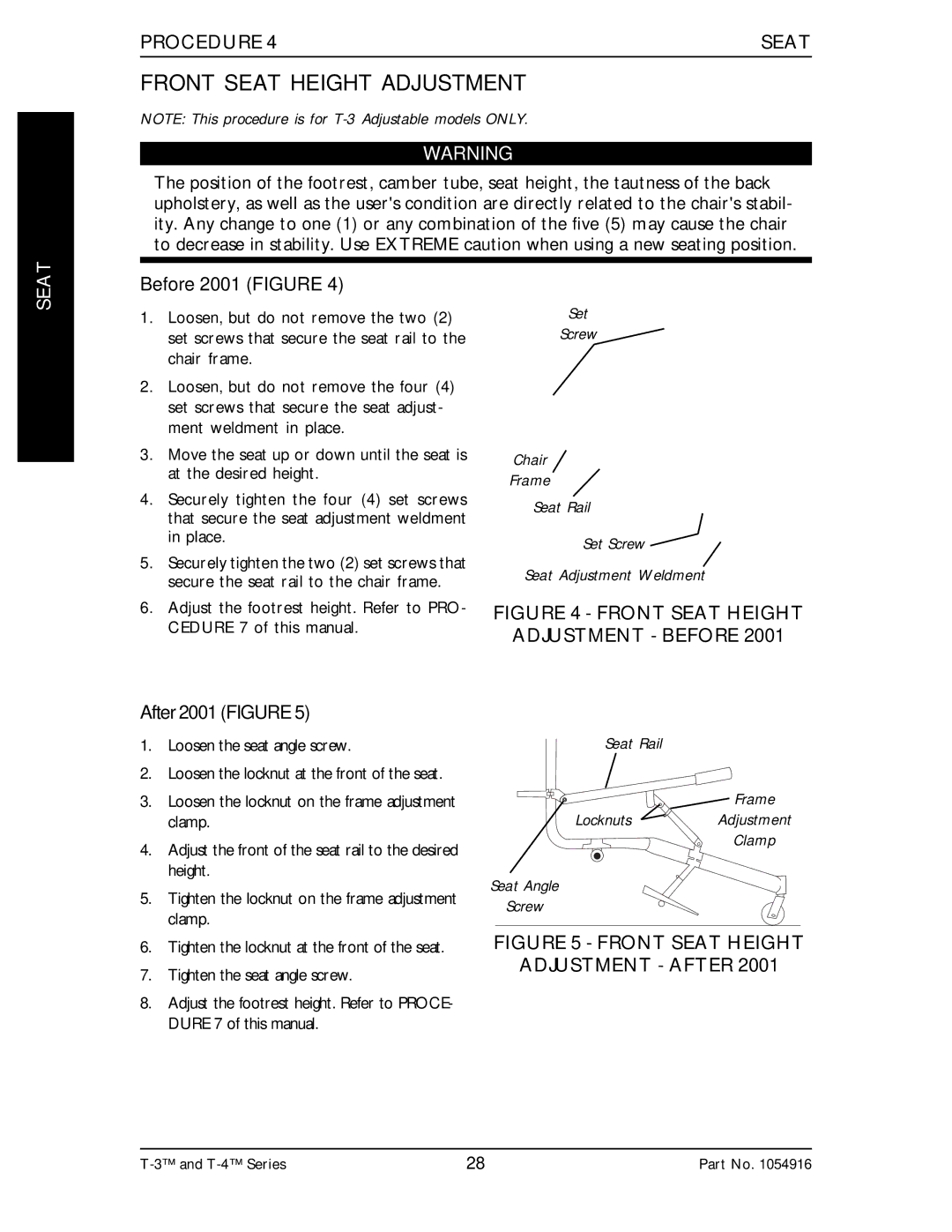
After 2001 (FIGURE 5)
1.Loosen the seat angle screw.
2.Loosen the locknut at the front of the seat.
3.Loosen the locknut on the frame adjustment clamp.
4.Adjust the front of the seat rail to the desired height.
5.Tighten the locknut on the frame adjustment clamp.
6.Tighten the locknut at the front of the seat.
7.Tighten the seat angle screw.
8.Adjust the footrest height. Refer to PROCE- DURE 7 of this manual.
Set
Screw
Chair
Frame
Seat Rail
Set Screw ![]()
Seat Adjustment Weldment
FIGURE 4 - FRONT SEAT HEIGHT
ADJUSTMENT - BEFORE 2001
Seat Rail
Frame
LocknutsAdjustment
Clamp
Seat Angle
Screw
FIGURE 5 - FRONT SEAT HEIGHT
ADJUSTMENT - AFTER 2001
28 | Part No. 1054916 |