WHEELS
PROCEDURE 6 | WHEELS |
|
|
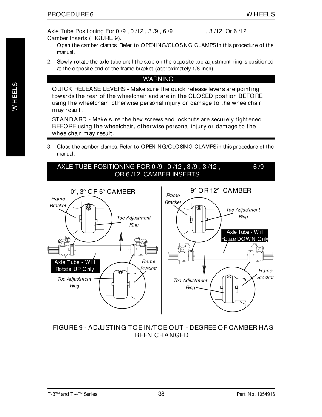
Axle Tube Positioning For 0°/9°, 0°/12°, 3°/9°, 6°/9° , 3°/12° Or 6°/12° Camber Inserts (FIGURE 9).
1.Open the camber clamps. Refer to OPENING/CLOSING CLAMPS in this procedure of the manual.
2.Slowly rotate the axle tube until the stop on the opposite toe adjustment ring is positioned at the opposite end of the frame bracket (approximately
WARNING
QUICK RELEASE LEVERS - Make sure the quick release levers are pointing towards the rear of the wheelchair and are in the CLOSED position BEFORE using the wheelchair, otherwise personal injury or damage to the wheelchair may result.
STANDARD - Make sure the hex screws and locknuts are securely tightened BEFORE using the wheelchair, otherwise personal injury or damage to the wheelchair may result.
3.Close the camber clamps. Refer to OPENING/CLOSING CLAMPS in this procedure of the manual.
AXLE TUBE POSITIONING FOR 0°/9°, 0°/12°, 3°/9°, 3°/12°, 6°/9°
OR 6°/12° CAMBER INSERTS
0°, 3° OR 6° CAMBER
Frame
Frame
9° OR 12° CAMBER
Bracket
Toe Adjustment
Ring
Axle Tube - Will | Frame |
Rotate UP Only | Bracket |
Toe Adjustment
Ring
Bracket
Toe Adjustment
Ring
Axle Tube - Will
Rotate DOWN Only
Frame
Toe Adjustment ![]()
![]() Bracket
Bracket
Ring
FIGURE 9 - ADJUSTING TOE IN/TOE OUT - DEGREE OF CAMBER HAS
BEEN CHANGED
38 | Part No. 1054916 |