REAR-PANEL CONNECTIONS
DIGITAL | ANALOG | VIDEO OUT | SCART |
AUDIO OUT | AUDIO OUT |
|
|
OPTICAL COAXIAL | L | Y/Y/G | VIDEO |
|
| TV | |
| R | Pb/Cb/B | Pr/Cr/R |
REMOTE | MODEL NO. DVD280 |
CONTROL |
|
IN | NORTHRIDGE,CA, USA |
| |
| Made in China |
OUT |
|
Maunfactured under license from Dolby Laboratories, "Dolby",and the
Confidential unpublished works, ![]() Laboratories. All rights reserved.
Laboratories. All rights reserved.
DTS and DTS Digital Out are trademarks of Digital Theater Systems Inc.
CAUTION | ATTENTION |
RISK OF ELECTRIC SHOCK | RISQUE D'ELECTROCUTION |
DO NOT OPEN | NE PAS OUVRIR |
WARNING : SHOCK HAZARD - DO NOT OPEN
AVIS : RISQUE DE CHOC ELECTRIQUE - NE PAS OUVRIR
AC INPUT
20W
CLASS 1 LASER PRODUCT KLASSE 1 LASER PRODUKT LUOKAN 1 LASER LAITE KLASS 1 LASER APPARAT
SERIAL NO.
¡ ™ £ ¢ ∞ § ¶ •ª
‚⁄
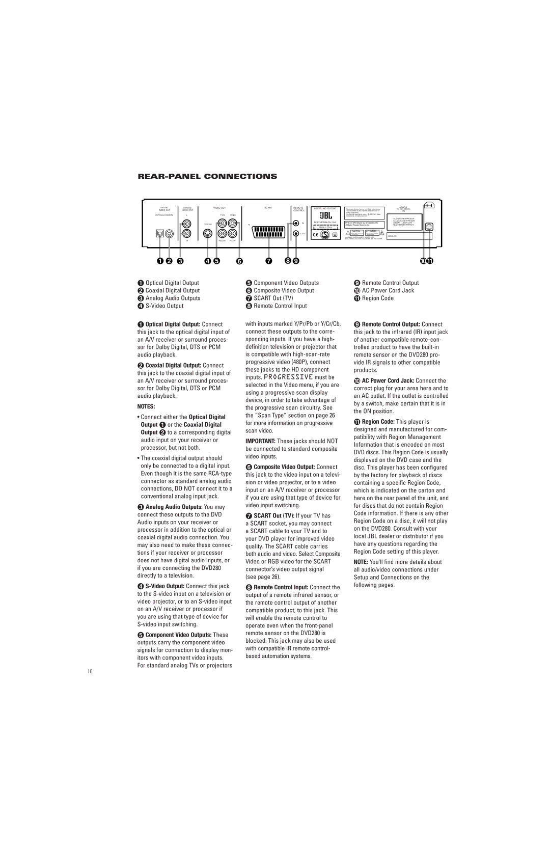
¡Optical Digital Output ™ Coaxial Digital Output £ Analog Audio Outputs ¢
¡Optical Digital Output: Connect this jack to the optical digital input of an A/V receiver or surround proces- sor for Dolby Digital, DTS or PCM audio playback.
™Coaxial Digital Output: Connect this jack to the coaxial digital input of an A/V receiver or surround proces- sor for Dolby Digital, DTS or PCM audio playback.
NOTES:
•Connect either the Optical Digital Output ¡ or the Coaxial Digital Output ™ to a corresponding digital audio input on your receiver or processor, but not both.
•The coaxial digital output should only be connected to a digital input. Even though it is the same
£Analog Audio Outputs: You may connect these outputs to the DVD Audio inputs on your receiver or processor in addition to the optical or coaxial digital audio connection. You may also need to make these connec- tions if your receiver or processor does not have digital audio inputs, or if you are connecting the DVD280 directly to a television.
¢
∞Component Video Outputs: These outputs carry the component video signals for connection to display mon- itors with component video inputs. For standard analog TVs or projectors
∞Component Video Outputs § Composite Video Output ¶ SCART Out (TV)
• Remote Control Input
with inputs marked Y/Pr/Pb or Y/Cr/Cb, connect these outputs to the corre- sponding inputs. If you have a high- definition television or projector that is compatible with
IMPORTANT: These jacks should NOT be connected to standard composite video inputs.
§Composite Video Output: Connect this jack to the video input on a televi- sion or video projector, or to a video input on an A/V receiver or processor if you are using that type of device for video input switching.
¶SCART Out (TV): If your TV has a SCART socket, you may connect a SCART cable to your TV and to your DVD player for improved video quality. The SCART cable carries both audio and video. Select Composite Video or RGB video for the SCART connector’s video output signal
(see page 26).
•Remote Control Input: Connect the output of a remote infrared sensor, or the remote control output of another compatible product, to this jack. This will enable the remote control to operate even when the
ªRemote Control Output ‚ AC Power Cord Jack ⁄ Region Code
ªRemote Control Output: Connect this jack to the infrared (IR) input jack of another compatible
‚AC Power Cord Jack: Connect the correct plug for your area here and to an AC outlet. If the outlet is controlled by a switch, make certain that it is in the ON position.
⁄Region Code: This player is designed and manufactured for com- patibility with Region Management Information that is encoded on most DVD discs. This Region Code is usually displayed on the DVD case and the disc. This player has been configured by the factory for playback of discs containing a specific Region Code, which is indicated on the carton and here on the rear panel of the unit, and for discs that do not contain Region Code information. If there is any other Region Code on a disc, it will not play on the DVD280. Consult with your local JBL dealer or distributor if you have any questions regarding the Region Code setting of this player.
NOTE: You’ll find more details about all audio/video connections under Setup and Connections on the following pages.
16