CONNECTION
Connecting audio signals
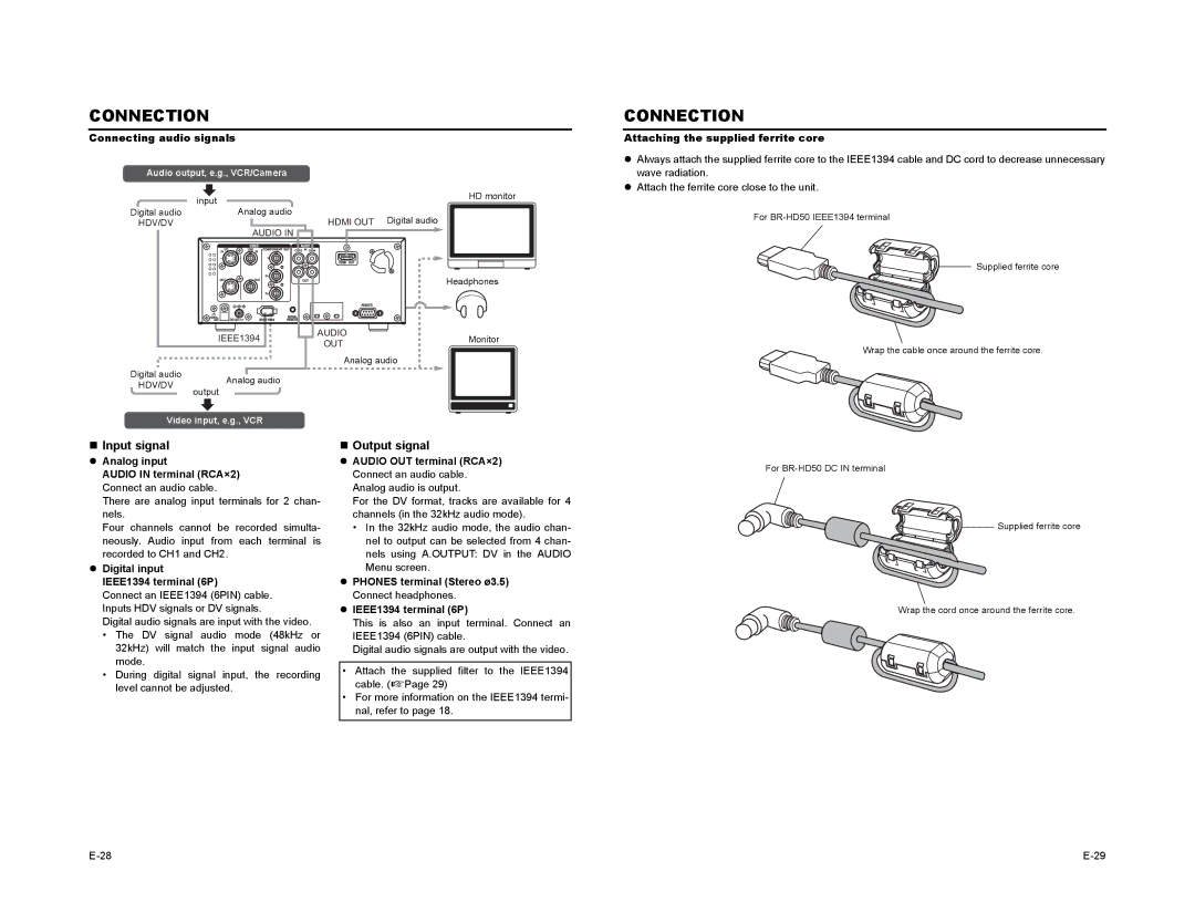
Audio output, e.g., VCR/Camera |
| ||||
|
|
|
|
| HD monitor |
|
|
|
|
| |
| input | ||||
|
| ||||
Digital audio |
|
| Analog audio | HDMI OUT Digital audio | |
HDV/DV |
|
|
|
| |
AUDIO IN
|
| Headphones | |
IEEE1394 | AUDIO | Monitor | |
OUT | |||
|
| ||
| Analog audio |
|
Digital audio |
|
|
|
| |
|
| Analog audio | |||
HDV/DV |
|
| |||
output | |||||
| |||||
|
|
|
| ||
Video input, e.g., VCR | |||||
CONNECTION
Attaching the supplied ferrite core
zAlways attach the supplied ferrite core to the IEEE1394 cable and DC cord to decrease unnecessary wave radiation.
zAttach the ferrite core close to the unit.
For
Supplied ferrite core
Wrap the cable once around the ferrite core.
Input signal z Analog input
AUDIO IN terminal (RCA×2) Connect an audio cable.
There are analog input terminals for 2 chan- nels.
Four channels cannot be recorded simulta- neously. Audio input from each terminal is recorded to CH1 and CH2.
z Digital input
IEEE1394 terminal (6P)
Connect an IEEE1394 (6PIN) cable. Inputs HDV signals or DV signals.
Digital audio signals are input with the video.
•The DV signal audio mode (48kHz or 32kHz) will match the input signal audio mode.
•During digital signal input, the recording level cannot be adjusted.
Output signal
zAUDIO OUT terminal (RCA×2) Connect an audio cable. Analog audio is output.
For the DV format, tracks are available for 4 channels (in the 32kHz audio mode).
•In the 32kHz audio mode, the audio chan- nel to output can be selected from 4 chan- nels using A.OUTPUT: DV in the AUDIO Menu screen.
zPHONES terminal (Stereo ø3.5) Connect headphones.
zIEEE1394 terminal (6P)
This is also an input terminal. Connect an IEEE1394 (6PIN) cable.
Digital audio signals are output with the video.
•Attach the supplied filter to the IEEE1394 cable. (XPage 29)
•For more information on the IEEE1394 termi- nal, refer to page 18.
For
Supplied ferrite core
Wrap the cord once around the ferrite core.