Controls and Features (cont.)
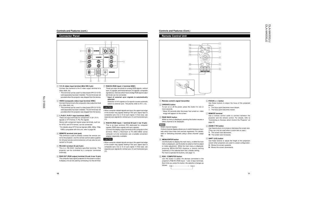
Connector Panel
|
|
| 1 | 2 |
|
|
|
| Y/C | VIDEO |
|
8 | RGB | RGB |
|
|
|
| R | RGB | EXT. IN | Y |
|
7 | G | H/CS |
| 3 | |
| B | V |
|
| |
|
|
| REMOTE |
|
|
| RGB OUT |
| CONTROL |
| |
|
|
|
| ||
| 6 | 5 | 4 |
|
|
Controls and Features (Cont.)
Remote Control Unit
r |
|
|
| 1 |
|
|
|
| |
| QUICK |
| OPERATE |
|
e | ALIGN. | AV HIDE | 2 | |
|
| |||
w | PRESET | PAGE BACK |
| |
LENS LOCK |
|
| 3 | |
| M | N |
| |
q |
|
| EN |
|
|
| T |
| |
|
|
| U/ |
|
| UNLOCK |
| E |
|
|
| E |
| |
|
|
| R | 4 |
|
|
|
| |
p | AV | RGB/COMPUTER | 5 | |
|
|
| ||
9 | U | T | + | 6 |
SHIFT | ZOOM | FOCUS | ||
| D | W | – |
|
|
| LENS |
|
|
8
No.51666
1Y/C (S video) input terminal (Mini DIN 4 pin)
Connect this terminal to the S video output terminal of a video deck, etc.
*This terminal can be used if a video board
2VIDEO (composite video) input terminal (BNC) Connect this terminal to the composite video output terminal of a video deck, etc.
*This terminal can be used if a video board
3Y, PB/B-Y, PR/R-Y input terminals (BNC)
These are input terminals for component (Y,
Device with component signal output terminals, such as for NTSC and
*For details about
4REMOTE terminal (mini jack)
This terminal is used to directly connect the remote con- trol to the projector. Use the remote control cable supplied. An infrared remote control extension unit can also be con- nected to the jack.
5RS-232C terminal (D-sub 9 pin)
This is a
6 RGB OUT (RGB output) terminal |
7RGB IN (RGB input) -2 terminal (BNC)
These are input terminals for analog RGB signals, vertical sync (V) signals, and horizontal sync (H) signals / composite signals(Cs). Devices which have analog RGB signal output terminals can be connected.
*Input of external sync signals is automatically detected.
Detection of H/V signals or Cs signals causes automatic switch to external sync. The priority order is H/V > Cs.
CAUTION
•When
(H).
8RGB IN (RGB input)
Connect the display output terminal of the computer to this terminal. When a Macintosh or
CAUTION
•When
(H).
1Remote control’s signal transmitter
2OPERATE button
To turn on or off the power, press this button for one or more seconds.
*About 30 seconds after the power has turned on, video image will appear on the screen.
3PAGE BACK button
While no menu is displayed, pressing this button causes a direct channel to be displayed.
Memo
Direct channel display:
A direct channel display allows you to switch between chan- nels which have lines and sources registered. For details, refer to “Switching channels using a direct channel” (page 52).
4MENU/ENTER button
Use this button to display the main menu, or while the main menu is displayed, use the button to select an item to adjust or make adjustment. While the main menu is displayed, pressing MENU/ENTER displays a details setting (submenu) if the selected item has a details setting.
For how to operate the buttons, see page 13.
5RGB / COMPUTER button
6FOCUS (+/–) button
Use these buttons to adjust the focus of the projected picture.
+: The focus point becomes more distant.
7REMOTE terminal
Use a remote control cable to connect between the projector and the remote control. For details, refer to “Connecting to Devices which Control the Projector” on page 22.
8ZOOM (T/W) button
Use these buttons to increase or decrease the screen size. (They can only be used when a zoom lens is used.)
T:The screen size decreases.
W:The screen size increases.
9SHIFT (U/D) button
Use these buttons to adjust the height of the projection screen when projectors are used in a stack configuration.
U:Moves the screen upwards.
D:Moves the screen downwards.
The computer input signal projected on the screen is output. |
A display unit can be used by connecting it to this terminal. |
Use this button to select the devices connected to the projector’s RGB IN (RGB input)
10 | 11 |