Filename [M150SEK_05Name.fm] |
|
M150SEK_00.book Page 16 Wednesday, June 15, 2005 4:04 PM | Masterpage:Left0 |
|
16 EN INSTALLING YOUR NEW UNIT
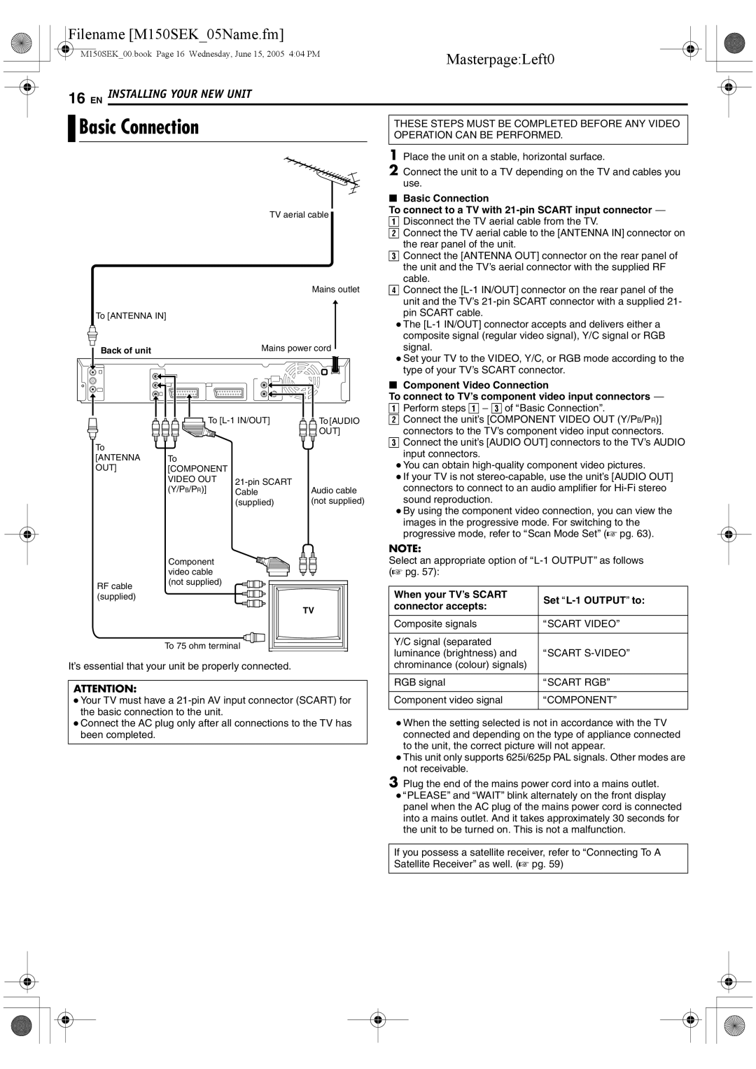
Basic Connection |
|
| THESE STEPS MUST BE COMPLETED BEFORE ANY VIDEO | ||
|
| OPERATION CAN BE PERFORMED. | |||
|
|
|
| 1 | Place the unit on a stable, horizontal surface. |
|
|
|
| 2 | Connect the unit to a TV depending on the TV and cables you |
|
|
|
|
| use. |
|
|
|
| 8 | Basic Connection |
|
| TV aerial cable | To connect to a TV with | ||
|
| A Disconnect the TV aerial cable from the TV. | |||
|
|
|
| ||
|
|
|
| B Connect the TV aerial cable to the [ANTENNA IN] connector on | |
|
|
|
|
| the rear panel of the unit. |
|
|
|
| C Connect the [ANTENNA OUT] connector on the rear panel of | |
|
|
|
|
| the unit and the TV’s aerial connector with the supplied RF |
|
|
|
|
| cable. |
|
|
| Mains outlet | D Connect the | |
|
|
|
|
| unit and the TV’s |
To [ANTENNA IN] |
|
|
|
| pin SCART cable. |
|
|
|
| ● The | |
|
|
|
|
| composite signal (regular video signal), Y/C signal or RGB |
Back of unit |
| Mains power cord |
| signal. | |
|
|
| ● Set your TV to the VIDEO, Y/C, or RGB mode according to the | ||
|
|
|
| ||
|
|
|
|
| type of your TV’s SCART connector. |
|
|
|
| 8 | Component Video Connection |
|
|
|
| To connect to TV’s component video input connectors ^ | |
|
|
|
| A Perform steps A - C of ABasic ConnectionB. | |
| To | To [AUDIO | B Connect the unit’s [COMPONENT VIDEO OUT (Y/PB/PR)] | ||
|
|
| OUT] |
| connectors to the TV’s component video input connectors. |
To |
|
|
| C Connect the unit’s [AUDIO OUT] connectors to the TV’s AUDIO | |
|
|
|
| input connectors. | |
[ANTENNA | To |
|
|
| |
|
| ● You can obtain | |||
OUT] | [COMPONENT |
|
| ||
|
| ● If your TV is not | |||
| VIDEO OUT |
| |||
| (Y/PB/PR)] | Audio cable |
| connectors to connect to an audio amplifier for | |
| Cable |
| |||
|
| (supplied) | (not supplied) |
| sound reproduction. |
● By using the component video connection, you can view the images in the progressive mode. For switching to the progressive mode, refer to AScan Mode SetB (A pg. 63).
RF cable (supplied)
Component video cable (not supplied)
NOTE:
Select an appropriate option of
When your TV’s SCART | Set | |
connector accepts: | ||
| ||
|
| |
Composite signals | ASCART VIDEOB | |
|
| |
Y/C signal (separated |
|
To 75 ohm terminal
It’s essential that your unit be properly connected.
ATTENTION:
●Your TV must have a
●Connect the AC plug only after all connections to the TV has been completed.
luminance (brightness) and | ASCART |
chrominance (colour) signals) |
|
|
|
RGB signal | ASCART RGBB |
|
|
Component video signal | ACOMPONENTB |
●When the setting selected is not in accordance with the TV connected and depending on the type of appliance connected to the unit, the correct picture will not appear.
●This unit only supports 625i/625p PAL signals. Other modes are not receivable.
3Plug the end of the mains power cord into a mains outlet.
●APLEASEB and AWAITB blink alternately on the front display panel when the AC plug of the mains power cord is connected into a mains outlet. And it takes approximately 30 seconds for the unit to be turned on. This is not a malfunction.
If you possess a satellite receiver, refer to AConnecting To A Satellite ReceiverB as well. (A pg. 59)