|
|
|
|
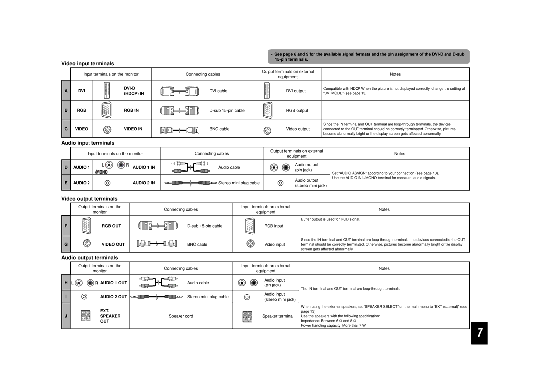
| • See page 8 and 9 for the available signal formats and the pin assignment of the | |||
Video input terminals |
|
|
|
| ||||
|
|
|
|
|
| |||
| Input terminals on the monitor | Connecting cables |
| Output terminals on external | Notes | |||
|
| equipment | ||||||
|
|
|
|
|
| |||
A | DVI |
| DVI cable |
|
| DVI output | Compatible with HDCP. When the picture is not displayed correctly, change the setting of | |
(HDCP) IN |
|
| “DVI MODE” (see page 13). | |||||
|
|
|
|
|
| |||
B | RGB | RGB IN |
| RGB output |
| |||
|
|
|
|
|
|
| Since the IN terminal and OUT terminal are | |
C | VIDEO | VIDEO IN | BNC cable |
|
| Video output | connected to the OUT terminal should be correctly terminated. Otherwise, pictures | |
|
|
|
|
|
|
| become abnormally bright or the display screen gets affected abnormally. | |
Audio input terminals |
|
|
|
|
|
| ||
| Input terminals on the monitor | Connecting cables |
| Output terminals on external | Notes | |||
|
|
| equipment | |||||
|
|
|
|
|
|
| ||
D | AUDIO 1 | AUDIO 1 IN | Audio cable |
|
| Audio output |
| |
|
| (pin jack) |
| |||||
|
|
|
|
|
| Set “AUDIO ASSIGN” according to your connection (see page 13). | ||
|
|
|
|
|
|
| ||
|
|
|
|
|
| Audio output | Use the AUDIO IN L/MONO terminal for monaural audio signals. | |
E | AUDIO 2 | AUDIO 2 IN | Stereo mini plug cable |
| ||||
(stereo mini jack) | ||||||||
|
|
|
|
|
| |||
Video output terminals |
|
|
|
|
|
| ||
| Output terminals on the |
| Connecting cables | Input terminals on external | Notes | |||
| monitor |
|
| equipment |
| |||
|
|
|
|
|
| |||
|
|
|
|
|
| Buffer output is used for RGB signal. | ||
F | RGB OUT |
|
|
| RGB input |
|
| |
|
|
|
|
|
| Since the IN terminal and OUT terminal are | ||
G | VIDEO OUT | BNC cable |
| Video input | terminal should be correctly terminated. Otherwise, pictures become abnormally bright or the display | |||
|
|
|
|
|
| screen gets affected abnormally. | ||
Audio output terminals |
|
|
|
|
|
| ||
| Output terminals on the |
| Connecting cables | Input terminals on external | Notes | |||
| monitor |
|
| equipment |
| |||
|
|
|
|
|
| |||
H | AUDIO 1 OUT | Audio cable |
| Audio input |
|
| ||
| (pin jack) |
|
| |||||
|
|
|
|
| The IN terminal and OUT terminal are | |||
|
|
|
|
|
| |||
I | AUDIO 2 OUT | Stereo mini plug cable |
| Audio input |
|
| ||
| (stereo mini jack) |
| ||||||
|
|
|
|
|
| |||
| EXT. |
|
|
|
| When using the external speakers, set “SPEAKER SELECT” on the main menu to “EXT (external)” (see | ||
|
|
|
|
| page 13). |
| ||
J | SPEAKER |
| Speaker cord |
| Speaker terminal Use the speakers with the following specification: | |||
| OUT |
|
|
|
| Impedance: Between 6 Ω and 8 Ω | ||
|
|
|
|
|
| Power handling capacity: More than 7 W | ||
7
