Installation
Precautions
•When installing the monitor on the wall, consult your dealer.
•Route the power cord and connection cables along the floor corners to avoid walking on them.
•For good heat dissipation, try to leave the following distance of space (minimum) around the monitor (see diagram below).
•When installing the monitor near the ceiling or similar location, the remote control may not work correctly because of possible effects, such as reflections, from the surroundings. If this happens, move the monitor where it is free from these effects.
•The ambient temperature of the installation place should be within the range of 0°C to 40°C (32°F to 104°F) (slightly variable depending on the ambient conditions of the installation place).
•Do not install the monitor in such a way that the monitor and other AV equipment affect each other adversely. (For example, if a disturbed image or noise due to electromagnetic interference occurs, or if the infrared remote control malfunctions, change the installation place.)
•Do not install the monitor in such a way that the ventilation holes of the internal cooling fans are blocked. Blocking the holes may cause high inside temperature and may damage the unit.
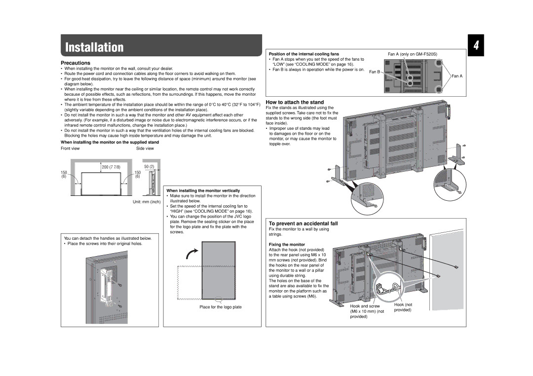
When installing the monitor on the supplied stand
Front view | Side view |
Position of the internal cooling fans | Fan A (only on | |
• | Fan A stops when you set the speed of the fans to |
|
| “LOW” (see “COOLING MODE” on page 16). |
|
• | Fan B is always in operation while the power is on. | Fan B |
|
| |
Fan A
How to attach the stand
Fix the stands as illustrated using the supplied screws. Take care not to fix the stands to the wrong side (the foot must face inside).
• Improper use of stands may lead to damages on the floor or on the monitor, or may cause the monitor to topple over.
4
150
(6)
200 (7 7/8)
50 (2)
150
(6)
Unit: mm (inch)
When installing the monitor vertically
•Make sure to install the monitor in the direction illustrated below.
•Set the speed of the internal cooling fan to “HIGH” (see “COOLING MODE” on page 16).
•You can change the position of the JVC logo plate. Remove the sealing sticker on the place for the logo plate and fix the plate with the screws.
To prevent an accidental fall
Fix the monitor to a wall by using strings.
You can detach the handles as illustrated below.
• Place the screws into their original holes.
Place for the logo plate
Fixing the monitor
Attach the hook (not provided) to the rear panel using M6 x 10 mm screws (not provided). Bind the hooks on the rear panel of the monitor to a wall or a pillar using durable string.
The holes on the base of the stand are also available to fix the monitor on the platform such as a table using screws (M6).
Hook and screw (M6 x 10 mm) (not provided)
Hook (not provided)