Using the serial communication
You can control the monitor from external control equipment (a personal computer or a dedicated controller) via the
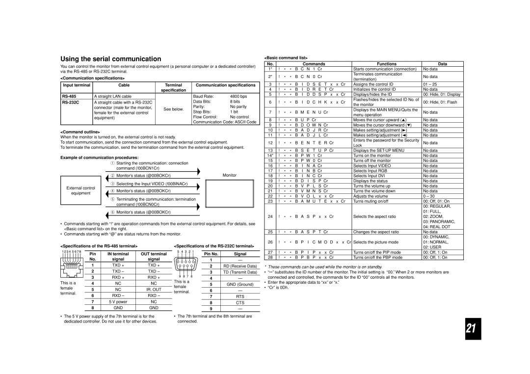
<Communication specifications>
Input terminal | Cable | Terminal | Communication specifications | |
|
| specification |
|
|
A straight LAN cable |
| Baud Rate: | 4800 bps | |
A straight cable with a |
| Data Bits: | 8 bits | |
| connector (male for the monitor, | See below. | Parity: | No parity |
| female for the external control | Stop Bits: | 1 bit | |
|
| |||
| equipment) |
| Flow Control: | No control |
|
|
| Communication Code: ASCII Code | |
<Command outline>
When the monitor is turned on, the external control is not ready.
To start communication, send the connection command from the external control equipment.
To terminate the communication, send the termination command from the external control equipment.
Example of communication procedures:
<Basic command list>
No. |
|
|
|
| Commands |
|
|
| Functions | Data | |||||
1* | ! | * | * | B | C | N | 1 | Cr |
|
|
|
| Starts communication (connection) | No data | |
2* | ! | * | * | B | C | N | 0 | Cr |
|
|
|
| Terminates communication | No data | |
|
|
|
| (termination) | |||||||||||
|
|
|
|
|
|
|
|
|
|
|
|
|
| ||
3 | ! | * | * | B | I | D | S | E | T | x | x | Cr | Assigns the control ID | 01 – 25 | |
4 | ! | * | * | B | I | D | R | E | T | Cr |
|
| Initializes the control ID | No data | |
5 | ! | * | * | B | I | D | D | S | P | x | x | Cr | Displays/hides the ID | 00: Hide, 01: Display | |
6 | ! | * | * | B | I | D | C | H | K | x | x | Cr | Flashes/hides the selected ID No. of | 00: Hide, 01: Flash | |
the monitor | |||||||||||||||
|
|
|
|
|
|
|
|
|
|
|
|
|
| ||
7 | ! | * | * | B | M | E | N | U Cr |
|
|
| Displays the MAIN MENU/Quits the | No data | ||
|
|
| menu operation | ||||||||||||
|
|
|
|
|
|
|
|
|
|
|
|
|
| ||
8 | ! | * | * | B | U | P Cr |
|
|
|
|
| Moves the cursor upward (5) | No data | ||
9 | ! | * | * | B | D | O W | N Cr |
|
|
| Moves the cursor downward (∞) | No data | |||
10 | ! | * | * | B | A | D | J | R | Cr |
|
|
| Makes setting/adjustment (3) | No data | |
11 | ! | * | * | B | A | D | J | L | Cr |
|
|
| Makes setting/adjustment (2) | No data | |
12 | ! | * | * | B | E | N | T | E | R Cr |
|
| Enters the password for the Security | No data | ||
|
| Lock | |||||||||||||
|
|
|
|
|
|
|
|
|
|
|
|
|
| ||
13 | ! | * | * | B | S | E | T | U | P Cr |
|
| Displays the | No data | ||
14* | ! | * | * | B | P | W | 1 | Cr |
|
|
|
| Turns on the monitor | No data | |
15 | ! |
|
| B | P | W | 0 | Cr |
|
|
|
| Turns off the monitor | No data | |
External control
equipment
1Starting the communication: connection command (!00BCN1Cr)
2 Monitor’s status (@00BOKCr) | Monitor |
3Selecting the Input VIDEO (!00BINACr)
4 Monitor’s status (@00BOKCr)
5Terminating the communication: termination
command (!00BCN0Cr)
![]() 6 Monitor’s status (@00BOKCr)
6 Monitor’s status (@00BOKCr)
|
| * | * |
|
|
|
|
|
|
|
|
|
16 | ! | * | * | B | I | N | A Cr |
|
| Selects Input VIDEO | No data | |
17 | ! | * | * | B | I | N | B Cr |
|
| Selects Input RGB | No data | |
18 | ! | * | * | B | I | N | C Cr |
|
| Selects Input DVI | No data | |
19 | ! | * | * | B | D | I | S | P | Cr |
| Displays the status | No data |
20 | ! | * | * | B | V P L S Cr |
| Turns the volume up | No data | ||||
21 | ! | * | * | B V M N S Cr |
| Turns the volume down | No data | |||||
22 | ! | * | * | B | V | O | L | x | x | Cr | Adjusts the volume | 0 – 30 |
23 | ! | * | * | B | A | M | U | T | E | x x Cr | Turns muting on/off | 00: Off, 01: On |
|
|
|
|
|
|
|
|
|
|
|
| 00: REGULAR, |
|
|
|
|
|
|
|
|
|
|
|
| 01: FULL, |
24 | ! | * | * | B | A | S | P | x | x | Cr | Selects the aspect ratio | 02: ZOOM, |
|
|
|
|
|
|
|
|
|
|
|
| 03: PANORAMIC, |
•Commands starting with “!” are operation commands from the external control equipment. For details, see <Basic command list> on the right.
•Commands starting with “@” are status returns from the monitor.
<Specifications of the |
| <Specifications of the | |||||||||||||||||||
|
|
|
|
|
|
|
|
|
|
|
|
|
|
|
|
|
|
|
|
|
|
|
|
|
|
|
|
|
|
|
|
|
|
|
|
| Pin | IN terminal |
| OUT terminal |
| Pin No. | Signal |
|
|
|
|
|
|
|
|
|
|
|
|
|
|
| No. | signal |
| signal |
| 1 | — |
|
|
|
|
|
|
|
|
|
|
|
|
|
|
|
|
| |||||
|
|
|
|
|
|
|
|
|
|
|
|
|
|
| 1 | TXD + |
| TXD + |
|
|
|
|
|
|
|
|
|
|
|
|
|
|
|
|
|
|
|
| 2 | RD (Receive Data) | |||
|
|
|
|
|
|
|
|
|
|
|
|
|
|
|
|
| |||||
|
|
|
|
|
|
|
|
|
|
|
|
|
|
| 2 | TXD – |
| TXD – |
| 3 | TD (Transmit Data) |
This is a |
| 3 | RXD + |
| RXD + | This is a | 4 | — | |||||||||||||
4 | NC |
| NC |
|
| ||||||||||||||||
| 5 | GND (Ground) | |||||||||||||||||||
| female | ||||||||||||||||||||
female | 5 | NC |
| IR. OUT |
|
| |||||||||||||||
| 6 | — | |||||||||||||||||||
| terminal. | ||||||||||||||||||||
terminal. |
| ||||||||||||||||||||
6 | RXD – |
| RXD – |
|
| ||||||||||||||||
|
| 7 | RTS | ||||||||||||||||||
|
|
|
|
|
|
|
|
|
|
|
|
|
|
|
|
| |||||
|
|
|
|
|
|
|
|
|
|
|
|
|
|
| 7 | 5 V power |
| NC |
|
|
|
|
|
|
|
|
|
|
|
|
|
|
|
|
|
|
|
| 8 | CTS | |||
|
|
|
|
|
|
|
|
|
|
|
|
|
|
| 8 | GND |
| GND |
|
|
|
|
|
|
|
|
|
|
|
|
|
|
|
|
|
|
|
| 9 | — | |||
|
|
|
| ||||||||||||||||||
• The 5 V power supply of the 7th terminal is for the | • The 7th terminal and the 8th terminal are | ||||||||||||||||||||
| dedicated controller. Do not use it for other devices. | connected. |
|
| |||||||||||||||||
|
|
|
|
|
|
|
|
|
|
|
| 04: REAL DOT |
25 | ! | * | * | B | A | S | P | T | Cr |
| Changes the aspect ratio | No data |
|
|
|
|
|
|
|
|
|
|
|
| 00: DYNAMIC, |
26 | ! | * | * | B | P | I | C | M | O | D x | x Cr Selects the picture mode | 01: NORMAL, |
|
|
|
|
|
|
|
|
|
|
|
| 02: USER |
27 | ! | * | * | B | P | I | P | x | x | Cr | Turns on/off the PIP mode | 00: Off, 1: On |
28 | ! | * | * | B | P | B | P | x | x | Cr | Turns on/off the PBP mode | 00: Off, 1: On |
* These commands can be used while the monitor is on standby.
•“**” substitutes the ID number of the monitor. The initial setting is “00.” When 2 or more monitors are connected and controlled, the commands for the ID “00” controls all the monitors.
•Enter the appropriate data to “xx” or “x.”
•“Cr” is 0Dh.
21