Input/output terminals
VIDEO IN | Video input | BNC terminal x 1 | 1 V |
VIDEO OUT | Video output | BNC terminal x 1 | 1 V |
RGB IN | RGB input | ||
| Video signal |
| G: 1 V |
|
|
| B, R: 0.7 V |
| Horizontal sync (HD) |
| HD: 2.0 V |
|
|
| negative polarity) |
| Vertical sync (VD) |
| VD: 2.0 V |
|
|
| (positive/negative polarity) |
RGB OUT | RGB input |
| |
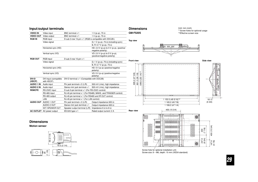
Dimensions
GM-F520S
Top view
Unit: mm (inch)
*1 Screw holes for optional usage *2 Effective screen size
*1
| Video signal |
| G: 1 V |
|
|
| B, R: 0.7 V |
| Horizontal sync (HD) |
| HD: 5 V |
|
|
| polarity) |
| Vertical sync (VD) |
| VD: 5 V |
|
|
| polarity) |
DVI input (compatible | |||
(HDCP) | with HDCP) |
|
|
AUDIO 1 IN | Audio input | Pin jack terminal x 2 (L/R) | 500 mV (rms), high impedance |
AUDIO 2 IN | Audio input | Stereo mini jack terminal x 1 | 500 mV (rms), high impedance |
REMOTE | |||
| |||
| |||
| LAN | ||
AUDIO OUT | AUDIO 1 OUT | Pin jack terminal x 2 (L/R) | Output impedance 600 Ω |
| AUDIO 2 OUT | Stereo mini jack terminal x 1 | Output impedance 600 Ω |
| EXT. SPEAKER OUT | Speaker output terminal (L/R) | Impedance 6 Ω to 8 Ω |
AC OUTLET | AC power output | IEC320 type x 1 | Rated output current: 2 A |
Dimensions
Front view
|
| 2 |
695.2 (27 3/8) | 661.2 (26 1/8) | 648.0 (25 1/4)* |
|
| 1 152.0 (45 5/16)*2 |
|
| 1 165.2 (45 7/8) |
|
| 1 199.2 (47 1/4) |
Rear view | 400 (15 3/4) | |
| ||
Side view
*1
161.5
(6 3/8)
Motion sensor
56 (2 1/4)
79.5 (3 1/4)
|
|
|
|
| 400 (15 3/4) |
| ||
200 | (7 7/8) |
|
|
| ||||
|
|
|
|
|
| |||
| 247.6 | (9 3/4) |
|
| (5 7/8) | |||
|
|
|
|
|
| |||
|
|
| ||||||
|
|
| 147.6 | |||||
|
|
|
|
|
|
|
|
|
28 | 1/8) |
| (1 |
Screw hole for optional installation unit.
Screw size: 8 – M6, depth: 15 mm (VESA standard)
29