Using the LAN system
Recommended | Operating system: | Microsoft® Windows® XP/Windows® Vista |
operating environment | Browser: | Microsoft® Internet Explorer® 6.0 and 7.0 |
Cable | Ethernet cable (Category 5 or higher) | |
To join the network
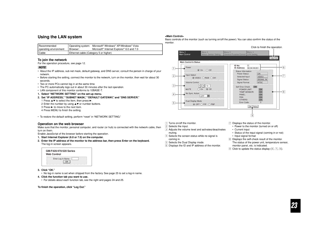
<Main Control>
Basic controls of the monitor (such as turning on/off the power). You can also confirm the status of the monitor.
|
|
| Click to finish the operation. |
Menu 1 | Menu 2 | Menu 3 | Menu 4 |
Main Control | Motion Sensor Setting | LAN Setting | |
|
|
| Log Out |
For the operation procedure, see page 12.
NOTE
•About the IP address, sub net mask, default gateway, and DNS server, consult the person in charge of your network.
•Before starting the setting, connect the monitor to the network, turn on the monitor, then wait for about 30 seconds.
•Two or more PCs cannot log in at the same time.
•The PC automatically logs out in about 30 minutes after the last operation.
•LAN component of this monitor conforms to
1.Select “NETWORK SETTING” on the
2.Set “IP ADDRESS,” “SUBNET MASK,” “DEFAULT GATEWAY,” and “DNS SERVER.” 1 Press 5∞ to select the item, then press 3.
2 Enter the number by using 5∞ or number buttons. 3 Press 3 to move to the next item.
4 Press MENU to finish the setting.
Main Control & Status
1 | Power |
| |
On | Off | ||
|
2Input Select
| VIDEO | RGB DVI |
Volume Control |
| |
3 | < > | 10 |
MUTE | On | Off |
4 | No Sync. Action | |
OFF | ||
|
5 | Dual Display Mode |
| |
OFF PIP | PBP | ||
|
ID No: | 1 |
|
|
|
|
|
|
ID Address: | xx. xx. xx.xx |
| |||||
Status Information |
|
|
|
|
| ||
Power Status: |
| ON | |||||
|
|
| |||||
Selected Input: |
| VIDEO | |||||
|
|
| |||||
Signal Status: |
| SIGNAL IN | |||||
|
|
| |||||
Signal Format: |
| NTSC | |||||
|
|
|
|
|
|
|
|
Self Error Check: | OK |
|
|
| |||
POWER UNIT: |
|
| OK |
| |||
|
|
|
|
|
| ||
TEMP. SENSOR: |
|
| OK |
| |||
|
|
|
|
|
| ||
PANEL: |
|
|
|
| OK |
| |
FAN: |
|
|
|
|
|
| |
|
|
|
| OK | |||
OTHERS: |
|
|
|
| |||
|
| OK | |||||
Error Code: |
| 0 |
|
| |||
Get Status |
6
7
8
• To restore the default setting, perform “reset” in “NETWORK SETTING.”
Operation on the web browser
Make sure that the monitor, personal computer, and router (or hub) is connected with the network cable, then turn on them.
Enable JavaScript of the browser before starting the operation.
1.Start Internet Explorer (6.0 or 7.0) on the computer.
2.Enter the IP address of the monitor to the address bar, then press Enter on the keyboard. The
Web Control
Enter Log In Name :
OK
1Turns on/off the monitor.
2 Selects the input.
3 Adjusts the volume level and activates/deactivates muting.
4 Selects the screen status while no signal is coming in.
5 Selects the Dual Display mode.
6 Displays the ID and IP address of the monitor.
9
7Displays the status of the monitor.
•Power to the monitor (turned on or off)
•Current input
•Status of the input signal (coming in or not)
•Input signal format
8Displays the
The status of the power unit, temperature sensor, monitor panel, etc. is indicated.
9Click to update the status display (6, 7, 8).
3.Click “OK.”
•No
4.Click the function tab you want to use.
•For details about each function tab, see the right and pages 24 and 25.
To finish the operation, click “Log Out.”
23