CONTROLS, INDICATORS AND CONNECTORS
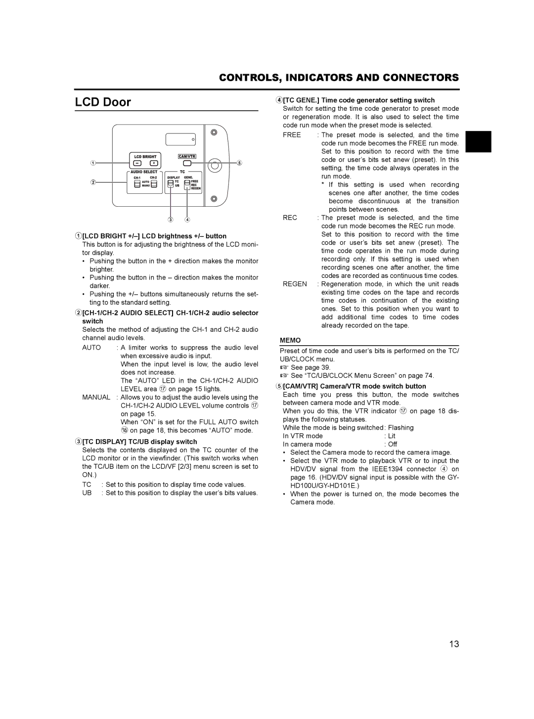
LCD Door
1 | 5 |
2
3 4
1[LCD BRIGHT +/–] LCD brightness +/– button
This button is for adjusting the brightness of the LCD moni- tor display.
•Pushing the button in the + direction makes the monitor brighter.
•Pushing the button in the – direction makes the monitor darker.
•Pushing the +/– buttons simultaneously returns the set- ting to the standard setting.
2[CH-1/CH-2 AUDIO SELECT] CH-1/CH-2 audio selector switch
Selects the method of adjusting the
AUTO | : A limiter works to suppress the audio level |
| when excessive audio is input. |
| When the input level is low, the audio level |
| does not increase. |
| The “AUTO” LED in the |
| LEVEL area g on page 15 lights. |
MANUAL | : Allows you to adjust the audio levels using the |
| |
| on page 15. |
| When “ON” is set for the FULL AUTO switch |
| h on page 18, this becomes “AUTO” mode. |
3[TC DISPLAY] TC/UB display switch
Selects the contents displayed on the TC counter of the LCD monitor or in the viewfinder. (This switch works when the TC/UB item on the LCD/VF [2/3] menu screen is set to ON.)
TC | : Set to this position to display time code values. |
UB | : Set to this position to display the user’s bits values. |
4[TC GENE.] Time code generator setting switch Switch for setting the time code generator to preset mode or regeneration mode. It is also used to select the time code run mode when the preset mode is selected.
FREE | : The preset mode is selected, and the time |
| code run mode becomes the FREE run mode. |
| Set to this position to record with the time |
| code or user’s bits set anew (preset). In this |
| setting, the time code always operates in the |
| run mode. |
| * If this setting is used when recording |
| scenes one after another, the time codes |
| become discontinuous at the transition |
| points between scenes. |
REC | : The preset mode is selected, and the time |
| code run mode becomes the REC run mode. |
| Set to this position to record with the time |
| code or user’s bits set anew (preset). The |
| time code operates in the run mode during |
| recording only. If this setting is used when |
| recording scenes one after another, the time |
| codes are recorded as continuous time codes. |
REGEN | : Regeneration mode, in which the unit reads |
| existing time codes on the tape and records |
| time codes in continuation of the existing |
| ones. Set to this position when you want to |
| add additional time codes to time codes |
| already recorded on the tape. |
MEMO
Preset of time code and user’s bits is performed on the TC/ UB/CLOCK menu.
X See page 39.
X See “TC/UB/CLOCK Menu Screen” on page 74.
5[CAM/VTR] Camera/VTR mode switch button
Each time you press this button, the mode switches between camera mode and VTR mode.
When you do this, the VTR indicator g on page 18 dis- plays the following statuses.
While the mode is being switched : Flashing
In VTR mode | : Lit |
In camera mode | : Off |
•Select the Camera mode to record the camera image.
•Select the VTR mode to playback VTR or to input the HDV/DV signal from the IEEE1394 connector 4 on page 16. (HDV/DV signal input is possible with the GY-
•When the power is turned on, the mode becomes the Camera mode.
13