CONTROLS, INDICATORS AND CONNECTORS
Indications on the LCD Monitor and in the Viewfinder (Cont’d)
| 1 | 2 |
|
| 3 |
7 |
|
|
0 |
|
|
|
| 4 |
9 | 8 6 | 5 |
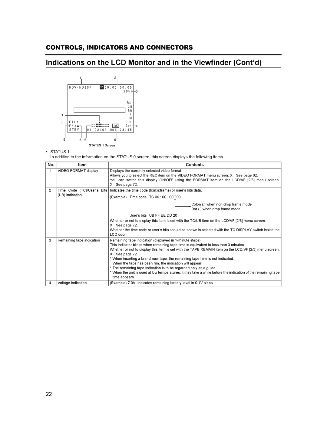
STATUS 1 Screen
•STATUS 1
In addition to the information on the STATUS 0 screen, this screen displays the following items.
No. | Item | Contents |
1 | VIDEO FORMAT display | Displays the currently selected video format. |
|
| Allows you to select the REC item on the VIDEO FORMAT menu screen. X See page 62. |
|
| You can switch this display ON/OFF using the FORMAT item on the LCD/VF [2/3] menu screen. |
|
| X See page 72. |
2Time Code (TC)/User’s Bits Indicates the time code (h:m:s:frame) or user’s bits data.
(UB) indication | (Example) Time code TC 00 : 00 : 00 : 00 |
|
Colon (:) when
Dot (.) when drop frame mode
User’s bits UB FF EE DD 20
Whether or not to display this item is set with the TC/UB item on the LCD/VF [2/3] menu screen.
X See page 72.
Whether the time code or user’s bits should be shown is selected with the TC DISPLAY switch inside the
LCD door.
3 Remaining tape indication | Remaining tape indication (displayed in |
| This indicator blinks when remaining tape time is equivalent to less than 3 minutes. |
| Whether or not to display this item is set with the TAPE REMAIN item on the LCD/VF [2/3] menu screen. |
| X See page 72. |
*When inserting a
*The remaining tape indication is to be regarded only as a guide.
*When the unit is used at low temperatures, it may take a while before the indication of the remaining tape time appears.
4 Voltage indication | (Example) 7.0V: Indicates remaining battery level in 0.1V steps. |
22
