CONTROLS, INDICATORS AND CONNECTORS
ZOOM Lens (Optional)
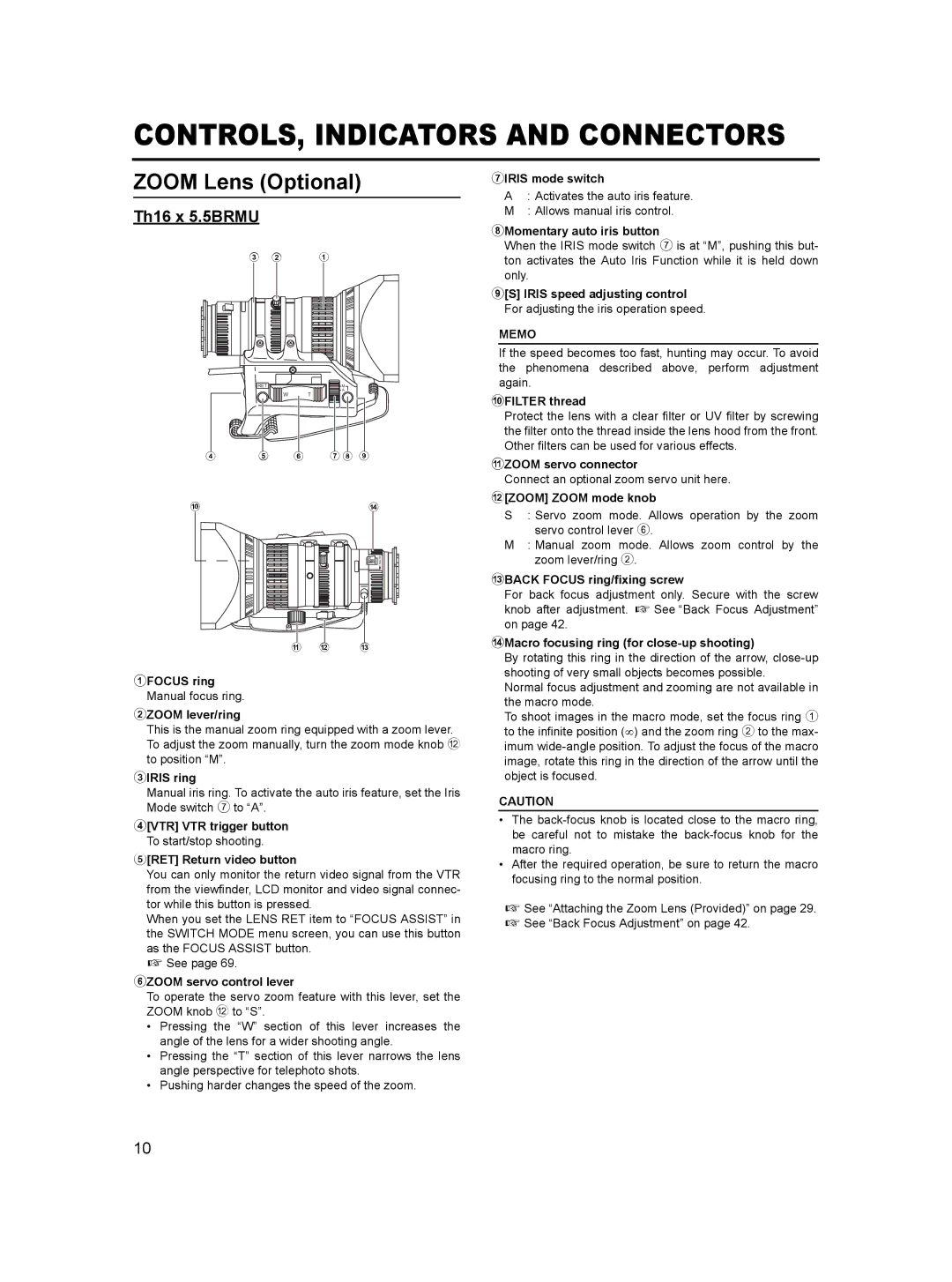
Th16 x 5.5BRMU
3 2 1
RET | M |
| A |
W | T |
|
|
|
|
|
|
|
|
|
4 | 5 | 6 | 7 8 9 | |||||
0d
MACRO
a b c
1FOCUS ring Manual focus ring.
2ZOOM lever/ring
This is the manual zoom ring equipped with a zoom lever. To adjust the zoom manually, turn the zoom mode knob b to position “M”.
3IRIS ring
Manual iris ring. To activate the auto iris feature, set the Iris Mode switch 7 to “A”.
4[VTR] VTR trigger button To start/stop shooting.
5[RET] Return video button
You can only monitor the return video signal from the VTR from the viewfinder, LCD monitor and video signal connec- tor while this button is pressed.
When you set the LENS RET item to “FOCUS ASSIST” in the SWITCH MODE menu screen, you can use this button as the FOCUS ASSIST button.
X See page 69.
6ZOOM servo control lever
To operate the servo zoom feature with this lever, set the ZOOM knob b to “S”.
•Pressing the “W” section of this lever increases the angle of the lens for a wider shooting angle.
•Pressing the “T” section of this lever narrows the lens angle perspective for telephoto shots.
•Pushing harder changes the speed of the zoom.
7IRIS mode switch
A: Activates the auto iris feature. M : Allows manual iris control.
8Momentary auto iris button
When the IRIS mode switch 7 is at “M”, pushing this but- ton activates the Auto Iris Function while it is held down only.
9[S] IRIS speed adjusting control For adjusting the iris operation speed.
MEMO
If the speed becomes too fast, hunting may occur. To avoid the phenomena described above, perform adjustment again.
0FILTER thread
Protect the lens with a clear filter or UV filter by screwing the filter onto the thread inside the lens hood from the front. Other filters can be used for various effects.
aZOOM servo connector
Connect an optional zoom servo unit here.
b[ZOOM] ZOOM mode knob
S : Servo zoom mode. Allows operation by the zoom servo control lever 6.
M: Manual zoom mode. Allows zoom control by the zoom lever/ring 2.
cBACK FOCUS ring/fixing screw
For back focus adjustment only. Secure with the screw knob after adjustment. X See “Back Focus Adjustment” on page 42.
dMacro focusing ring (for close-up shooting)
By rotating this ring in the direction of the arrow,
Normal focus adjustment and zooming are not available in the macro mode.
To shoot images in the macro mode, set the focus ring 1 to the infinite position (∞) and the zoom ring 2 to the max- imum
CAUTION
•The
•After the required operation, be sure to return the macro focusing ring to the normal position.
X See “Attaching the Zoom Lens (Provided)” on page 29. X See “Back Focus Adjustment” on page 42.
10