CONTROLS, INDICATORS AND CONNECTORS
Right Side Section
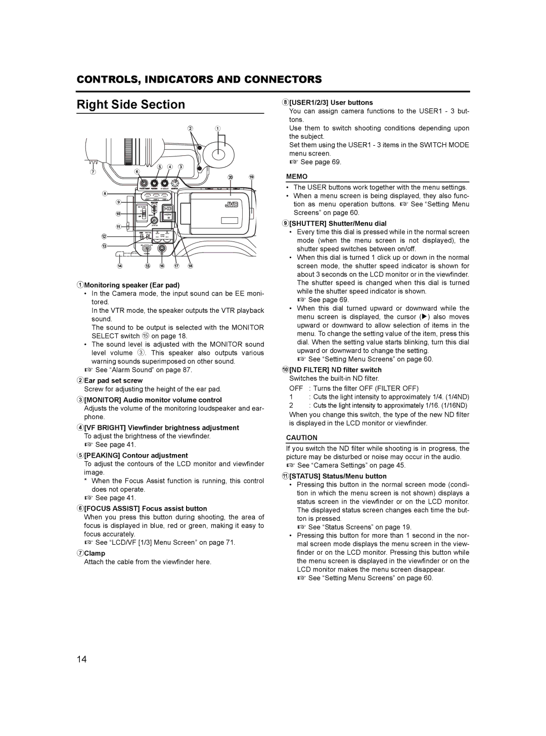
8[USER1/2/3] User buttons
You can assign camera functions to the USER1 - 3 but- tons.
7 6
2 1
5 4 3
j i
Use them to switch shooting conditions depending upon the subject.
Set them using the USER1 - 3 items in the SWITCH MODE menu screen.
X See page 69.
MEMO
|
|
|
|
| VF BRIGHT |
8 |
|
|
|
|
|
| 9 |
| USER 1 USER 2 | USER 3 | |
|
|
|
|
| |
|
| ND FILTER |
|
| |
| 0 | 2 |
|
|
|
| 1 |
|
|
| |
|
| MENU |
|
| |
| a |
| STATUS |
| |
|
|
| WHT.BAL | AUTO | AUTO |
b |
|
|
|
| AUDIO |
|
|
|
| LEVEL | |
c |
| ON | OFF |
|
|
POWER REC
d e f g h
1Monitoring speaker (Ear pad)
•In the Camera mode, the input sound can be EE moni- tored.
In the VTR mode, the speaker outputs the VTR playback sound.
The sound to be output is selected with the MONITOR SELECT switch e on page 18.
•The sound level is adjusted with the MONITOR sound level volume 3. This speaker also outputs various
warning sounds superimposed on other sound. X See “Alarm Sound” on page 87.
2Ear pad set screw
Screw for adjusting the height of the ear pad.
3[MONITOR] Audio monitor volume control
Adjusts the volume of the monitoring loudspeaker and ear- phone.
4[VF BRIGHT] Viewfinder brightness adjustment To adjust the brightness of the viewfinder.
X See page 41.
5[PEAKING] Contour adjustment
To adjust the contours of the LCD monitor and viewfinder image.
*When the Focus Assist function is running, this control does not operate.
X See page 41.
6[FOCUS ASSIST] Focus assist button
When you press this button during shooting, the area of focus is displayed in blue, red or green, making it easy to focus accurately.
X See “LCD/VF [1/3] Menu Screen” on page 71.
7Clamp
Attach the cable from the viewfinder here.
•The USER buttons work together with the menu settings.
•When a menu screen is being displayed, they also func- tion as menu operation buttons. X See “Setting Menu Screens” on page 60.
9[SHUTTER] Shutter/Menu dial
•Every time this dial is pressed while in the normal screen mode (when the menu screen is not displayed), the shutter speed switches between on/off.
•When this dial is turned 1 click up or down in the normal screen mode, the shutter speed indicator is shown for about 3 seconds on the LCD monitor or in the viewfinder. The shutter speed is changed when this dial is turned while the shutter speed indicator is shown.
X See page 69.
•When this dial turned upward or downward while the menu screen is displayed, the cursor (K) also moves upward or downward to allow selection of items in the menu. To change the setting value of the item, press this dial. When the setting value starts blinking, turn this dial upward or downward to change the setting.
X See “Setting Menu Screens” on page 60.
0[ND FILTER] ND filter switch Switches the built-in ND filter.
OFF : Turns the filter OFF (FILTER OFF)
1: Cuts the light intensity to approximately 1/4. (1/4ND)
2: Cuts the light intensity to approximately 1/16. (1/16ND)
When you change this switch, the type of the new ND filter is displayed in the LCD monitor or viewfinder.
CAUTION
If you switch the ND filter while shooting is in progress, the picture may be disturbed or noise may occur in the audio. X See “Camera Settings” on page 45.
a[STATUS] Status/Menu button
•Pressing this button in the normal screen mode (condi- tion in which the menu screen is not shown) displays a status screen in the viewfinder or on the LCD monitor. The displayed status screen changes each time the but- ton is pressed.
X See “Status Screens” on page 19.
•Pressing this button for more than 1 second in the nor- mal screen mode displays the menu screen in the view- finder or on the LCD monitor. Pressing this button while the menu screen is displayed in the viewfinder or on the LCD monitor makes the menu screen disappear.
X See “Setting Menu Screens” on page 60.
14
