Filename
|
8 EN | INDEX (cont.) |
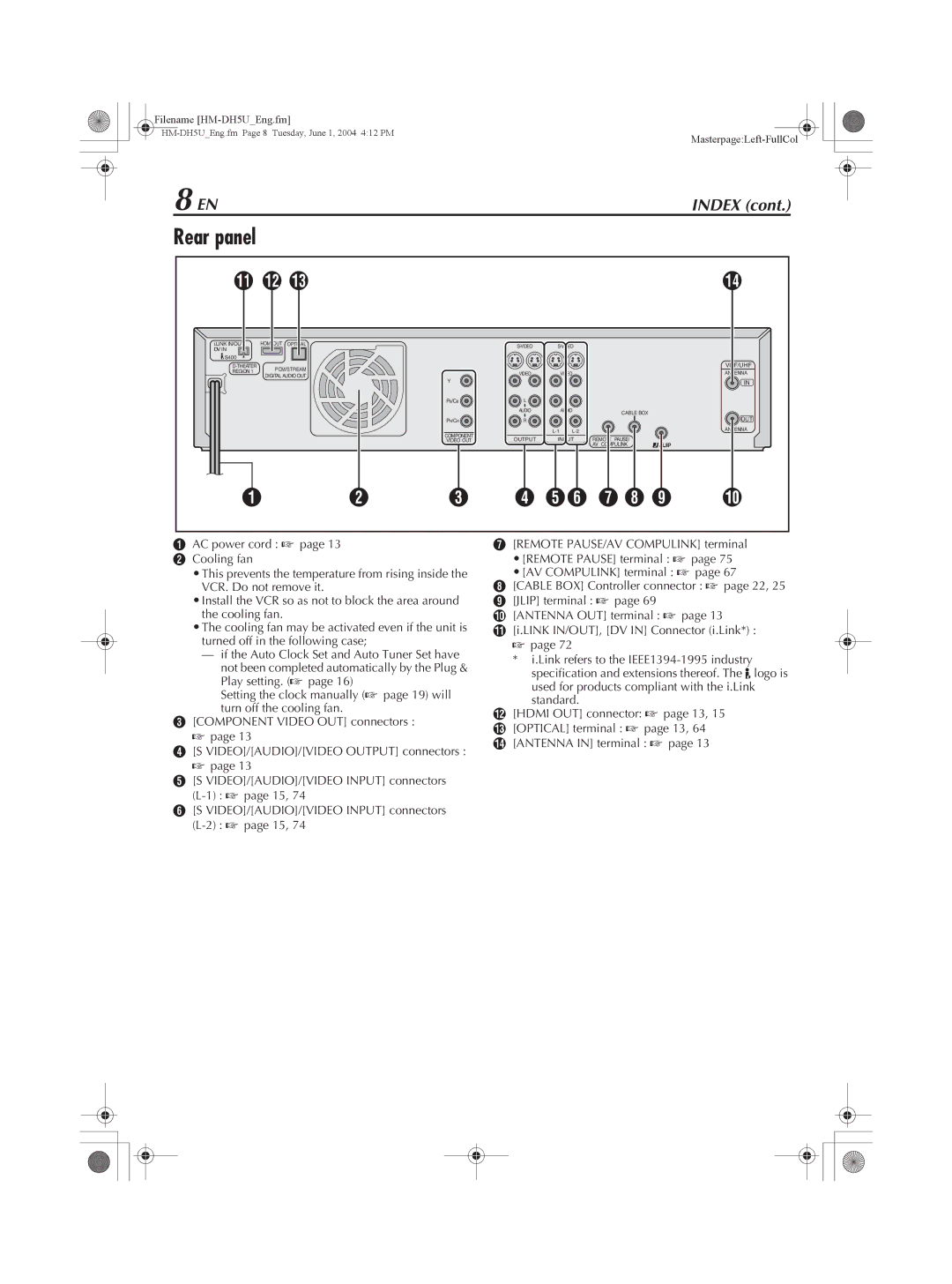
Rear panel
K L M |
|
|
|
|
| N | ||
i.LINK IN/OUT | HDMI OUT | OPTICAL |
|
|
| |||
DV IN |
|
|
|
|
| |||
|
|
|
|
|
|
|
| |
S400 |
|
|
|
|
|
|
|
|
PCM/STREAM |
|
|
|
|
| VHF/UHF | ||
REGION 1 |
| VIDEO |
| VIDEO |
| ANTENNA | ||
DIGITAL AUDIO OUT |
|
|
| |||||
| Y |
|
|
|
|
| ||
|
|
|
|
|
|
| IN | |
|
|
| PB/CB | L |
| L |
|
|
|
|
|
| AUDIO |
| AUDIO | CABLE BOX |
|
|
|
|
|
|
|
| OUT | |
|
|
| PR/CR | R |
| R |
| |
|
|
|
|
|
| ANTENNA | ||
|
|
| COMPONENT | OUTPUT | INPUT | REMOTE PAUSE/ |
| |
|
|
| VIDEO OUT |
| ||||
|
|
|
|
|
|
| AV COMPULINK |
|
A | B | C | D EF G H I | J | ||||
AAC power cord : A page 13
BCooling fan
•This prevents the temperature from rising inside the VCR. Do not remove it.
•Install the VCR so as not to block the area around the cooling fan.
•The cooling fan may be activated even if the unit is turned off in the following case;
—if the Auto Clock Set and Auto Tuner Set have not been completed automatically by the Plug & Play setting. (A page 16)
Setting the clock manually (A page 19) will turn off the cooling fan.
C[COMPONENT VIDEO OUT] connectors : A page 13
D[S VIDEO]/[AUDIO]/[VIDEO OUTPUT] connectors : A page 13
E[S VIDEO]/[AUDIO]/[VIDEO INPUT] connectors
F[S VIDEO]/[AUDIO]/[VIDEO INPUT] connectors
G[REMOTE PAUSE/AV COMPULINK] terminal
•[REMOTE PAUSE] terminal : A page 75
•[AV COMPULINK] terminal : A page 67
H[CABLE BOX] Controller connector : A page 22, 25
I[JLIP] terminal : A page 69
J[ANTENNA OUT] terminal : A page 13
K[i.LINK IN/OUT], [DV IN] Connector (i.Link*) : A page 72
* i.Link refers to the
L[HDMI OUT] connector: A page 13, 15
M[OPTICAL] terminal : A page 13, 64
N[ANTENNA IN] terminal : A page 13