Filename
|
12 EN |
|
|
|
|
| INSTALLING YOUR NEW VCR | ||
Connections |
|
|
|
| ||||
| To [i.LINK |
|
|
|
|
|
|
|
| IN/OUT] |
|
| i.LINK Cable (not supplied) | To i.LINK Input/Output Connector | |||
|
|
|
|
| Flat Feeder |
|
| |
|
|
|
|
|
|
| Antenna or Cable |
|
|
| Matching Transformer | Coaxial Cable |
|
| |||
|
|
|
|
|
| |||
|
|
| (not supplied) | To [ANTENNA IN] |
| Integrated HDTV | ||
| Back of VCR |
|
|
| (Antenna or cable | Antenna or Cable |
| |
|
|
|
|
| input) |
| ||
DV IN | HDMI OUT OPTICAL |
|
|
|
| for digital broadcast |
| |
i.LINK IN/OUT |
| To [ANTENNA |
|
| ||||
REGION 1 | DIGITAL AUDIO OUT | VIDEO | VIDEO | ANTENNA |
|
| ||
S400 |
|
|
|
|
|
|
|
|
PCM/STREAM |
|
| VHF/UHF |
|
|
|
| |
| Y |
|
| IN | OUT] | RF Cable (supplied) |
| |
| PB/CB | L | L |
|
|
| ||
|
| AUDIO | AUDIO | CABLE BOX |
|
|
|
|
| PR/CR | R | R | OUT |
|
|
|
|
| COMPONENT |
| ANTENNA |
|
|
|
| |
| VIDEO OUT | OUTPUT | INPUT | REMOTE PAUSE/ |
|
| To 75K terminal |
|
|
|
|
| AV COMPULINK |
|
|
| |
|
|
| To |
| To |
| ||
AC Outlet |
|
|
| (supplied) | Connector | To HDMI | ||
|
|
|
| |||||
|
|
|
|
|
|
| Connector | |
|
|
|
|
|
| Video Cable | To Video | |
|
|
| To [VIDEO OUTPUT] | OR |
| |||
|
| VIDEO | (not supplied) | Input Connector |
| |||
|
| L | To [AUDIO OUTPUT] |
| Audio Cable |
|
| |
|
| AUDIO |
|
|
| (supplied) |
|
|
|
| R |
|
|
|
|
|
|
|
| OUTPUT |
|
|
| To Audio Input Connectors |
| |
|
|
|
|
|
|
| ||
|
|
|
| Component Video Cable (not supplied) |
| |||
|
|
| To [COMPONENT |
| To Component Video Connectors |
| ||
|
|
| VIDEO OUTPUT] |
|
|
|
| |
|
|
|
| HDMI Cable (not supplied) |
| |||
|
|
| To [HDMI OUT] |
|
|
|
| |
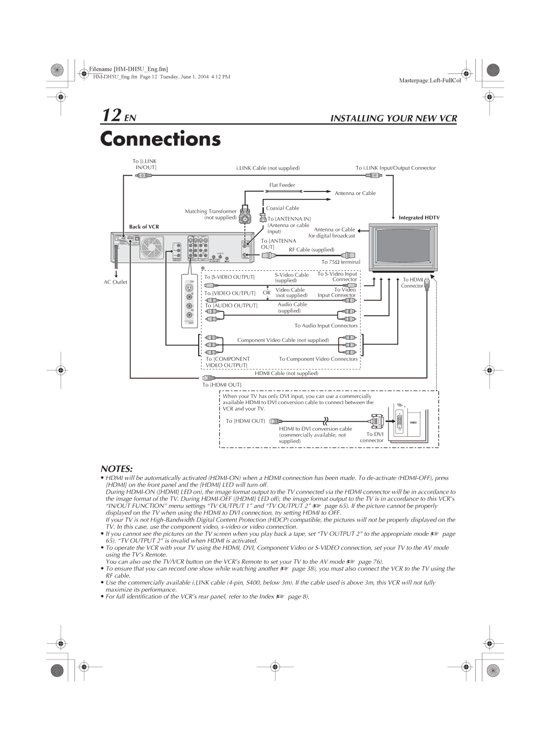
When your TV has only DVI input, you can use a commercially available HDMI to DVI conversion cable to connect between the VCR and your TV.
To [HDMI OUT]
HDMI to DVI conversion cable
(commercially available, not To DVI
supplied)connector
DIGITAL IN
R
AUDIO
L
VIDEO
NOTES:
•HDMI will be automatically activated
During
the image format of the TV. During
If your TV is not
•If you cannot see the pictures on the TV screen when you play back a tape, set “TV OUTPUT 2” to the appropriate mode (A page 65). “TV OUTPUT 2” is invalid when HDMI is activated.
•To operate the VCR with your TV using the HDMI, DVI, Component Video or
using the TV’s Remote.
You can also use the TV/VCR button on the VCR’s Remote to set your TV to the AV mode (A page 76).
•To ensure that you can record one show while watching another (A page 38), you must also connect the VCR to the TV using the RF cable.
•Use the commercially available i.LINK cable
•For full identification of the VCR’s rear panel, refer to the Index (A page 8).
