XL-R5020BK
Important for Laser Products
For U.S.A
Table of Contents
Introduction
Precautions
Playback
Precautions on Disc Playback and Recording
Recording
Important notice
Parts Identification
See pages in the parentheses for details
STANDBY/ON
To cancel the reset, press Cancel
To operate 3-CD Changer, press Control CD
To operate CD Recorder, press Control CDR
Supplied Accessories
Putting the Batteries into the Remote Control
Getting Started
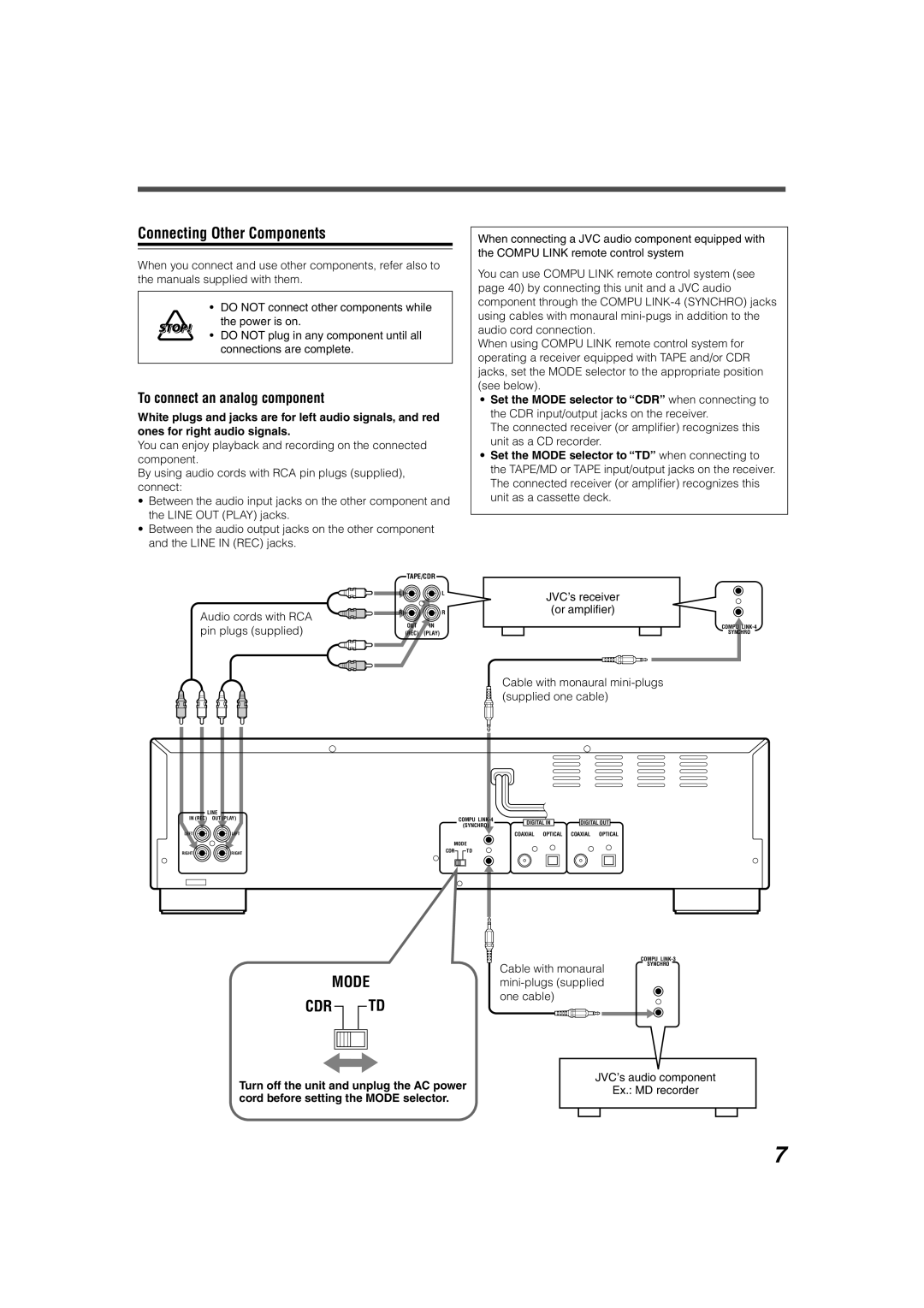
To connect an analog component
Connecting Other Components
To connect digital components
Audio component with digital output
Audio component with digital input
Listening with Headphones
Turning On and Off the Power
To increase the volume level, turn Phone Level control to
Basic Operations
Loading Discs
Playing Back Discs on 3-CD Changer
Playing Back All Loaded Discs-Continuous Play
On the unit only
To start playing a disc during playback of another disc
Basic Disc Operations
To go to another track
To go to another track directly
Programing the Playing Order of the Tracks-Program Play
To modify the program
To check the programed contents
Random indicator also lights up on the display
Play 3 Stop Play Mode
Playing at Random-Random Play
CD Changer Multi JOG ¢ Disc trays
Repeating Tracks-Repeat Play
Adjusting the Playback Speed-Pitch Control
Prohibiting Disc Ejection-Tray Lock
Press Pitch + or − during play
Loading a Disc Playing Back a Disc-Normal Play
Playing Back a Disc on CD Recorder
Press Eject
Press Eject 0 again
Load a disc onto the CD Recorder disc tray see
CDR
Press Control CDR, then
Playing Back MP3 Discs on 3-CD Changer
About MP3
MP3 Disc Structure
Pause Play Stop
Playing Back MP3 Discs
Buttons
Track numbers already played go off from the display
To go to another track within a group directly
Basic MP3 Disc Operations
To go to another group
To go to another group directly
Before You Start Recording
Recording on a CD-R/CD-RW
Press ¶ REC/REC Muting
Recording Manually-Standard Recording
Start recording
Press one of the disc number buttons CD1, CD2, CD3 you want
Press SET or Menu to finish the adjustment
To adjust the analog recording level
REC Level +/−
Menu SET
To make a silent portion while recording
To fade in and out recording-only for analog source
To change the display information while recording
Preparing for CD Synchronized Recording
Changing the recording speed
Finalizing discs automatically
CD REC ¶ Cancel
Recording from 3-CD Changer-CD Synchronized Recording
Disc Direct Recording
Recording the entire disc without any interruption
Normal initial setting appears on the display
Multi JOG ¢
To release the seamless recording, select Normal
CD REC 
One Track Recording
Stop 7 for
CD REC
To erase all programed tracks, press Cancel in step
To skip the currently playing track, press Cancel
Listening Edit Recording
To program other tracks, repeat step
Program Edit Recording
Press Synchro
Start playback of the selected external component
Recording from the Two Sources Mixed-Sound Mixing Recording
MIX Balance Selector
Pause REC Muting ¶ REC/REC Muting
Other Recording Functions
Finalizing a disc-CD-R/CD-RW
Press Finalize again to finalize a disc
Auto TR on initial setting appears on the display
Sync ALL initial setting appears on the display
Recording track marks manually
To use Synchronized Recording for recording all tracks
Separating recording tracks automatically
Turning on or off sampling frequency rate converter
Recording skip marks onto a CD-R/CD-RW-Track Skip
Erasing all tracks only for CD-RW-Disc Erase
Erasing tracks only for CD-RW-Track Erase
Load an unfinalized disc on the CD Recorder disc tray
Load a recorded disc on the CD Recorder disc tray
Setting the Clock
Using the Timer
To adjust the clock again
To set the clock first time
How Timers actually work
Using Daily Timer and Once Timer
STANDBY/ON Menu SET Cancel
Unit enters off-time setting mode
Setting Recording Timer
Setting Playing Timer
Timer Priority
To turn on Playing Timer or Recording Timer
Connection
Compu Link Remote Control System
Available functions
Automatic source selection
Maintenance
Glossary
Message
Signification Solution
Symptom Possible Cause Action
Troubleshooting
Specifications
Authorized Service Centers
Limited Warranty
0502KTYMDWJEM

