Connection and Setup
The following section is intended specifically for specialist dealers. You only need to pay attention to this section if you are carrying out the installation yourself.
The “Connection diagram ” section contains a sample configuration.
Do not connect the unit to the mains until all installation work has been properly carried out. Refer to the information in the
“Safety instructions” section.
Connecting the Unit
If you will be using the UFD 170 in conjunction with a CAP 210 or
CAP 310 from Kathrein, the installation instructions for the relevant
CAP unit must be followed during installation.
SAT-IF Connection
Connect the
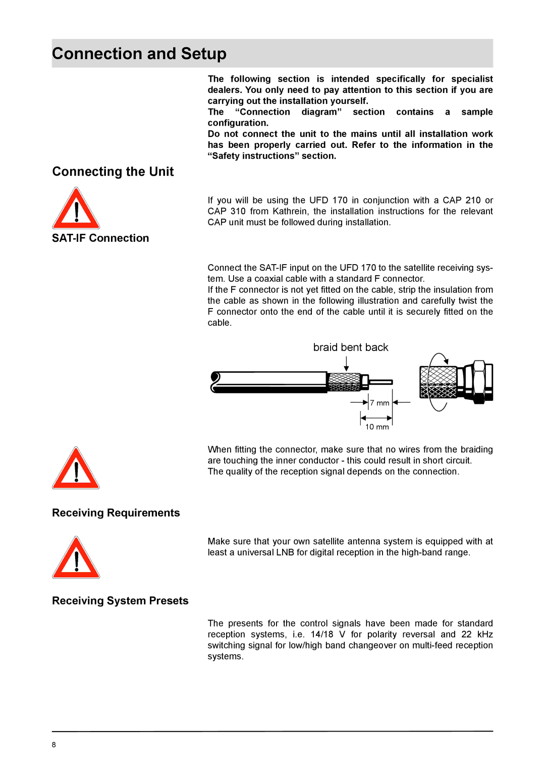
If the F connector is not yet fi tted on the cable, strip the insulation from the cable as shown in the following illustration and carefully twist the F connector onto the end of the cable until it is securely fi tted on the cable.
braid bent back
7 mm
10 mm
When fi tting the connector, make sure that no wires from the braiding are touching the inner conductor - this could result in short circuit.
The quality of the reception signal depends on the connection.
Receiving Requirements
Make sure that your own satellite antenna system is equipped with at least a universal LNB for digital reception in the
Receiving System Presets
The presents for the control signals have been made for standard reception systems, i.e. 14/18 V for polarity reversal and 22 kHz switching signal for low/high band changeover on
8