I
÷
IMPORTANTSAFETY
INSTRUCTIONS
Step 2
A.Wood Construction:
1.Roor. Drilla _' pilothoaein the centerof each
AND
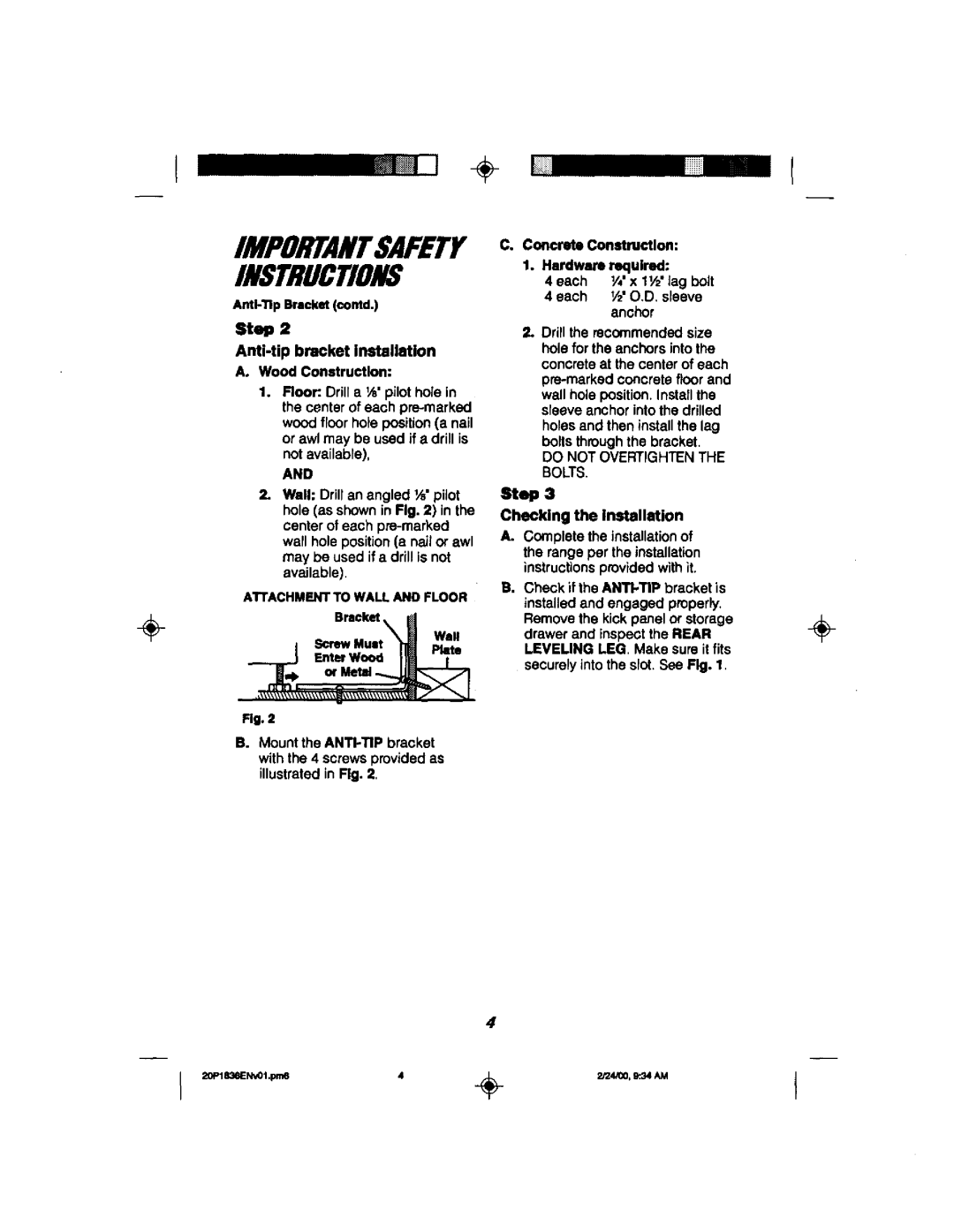
2.Wall: Drillan angled _" pilot hole (as shownin Fig. 2) in the center of each
A'rrACHMENTTOWALLANDFLOOR
Bracket
I ScrewMunt "_ Plate
__..._j F.==w_ Im T
Rg. 2
B.Mount
C. Concrete Construction: |
|
1. Hardware required: |
|
4 each V,' x 11/2'lag bolt |
|
4 each V£ O.D. sleeve |
|
anchor |
|
2. Drillthe recommendedsize |
|
hole for the anchors intothe |
|
concreteat the center of each |
|
| |
wall hole position.Installthe |
|
sleeve anchorintothe drilled |
|
holesand then installthe lag |
|
boltsthroughthe bracket. |
|
DO NOT OVERTIGHTENTHE |
|
BOLTS. |
|
Step 3 |
|
Checking the installation |
|
A. Complete the installationof |
|
the rangeper the installation |
|
instructionsprovidedwithit. |
|
B. Check if the ANTI.TIP bracket is |
|
installedand engaged properly. | ÷ |
Removethe kick panelor storage | |
drawerand inspeotthe REAR | |
LEVEUNG LEG. Make sure it fits |
|
securelyintothe slot.See Fig. 1. |
|
4