Kirby Morgan 37 & 57
|
|
| Balance |
Inlet valve | spacer |
| |
| Spring |
Main tube |
|
Bearing | Seat |
clip |
|
![]() Lever
Lever
![]()
![]()
Adjustment nipple
8)Remove the adjustment shaft from the flex knob. With the shaft out, grab the packing nut with one hand and the flex knob with the other and bend. There is a boss on the knob that will pop loose from the packing nut.
9)Remove the
10)Remove the lever by gently pulling one leg out from the slot on the main tube, followed by the sec- ond leg.
9)Remove the bearing clip from the main tube.
10)Slide the balance spacer, spring, inlet valve as- sembly out from the main tube.
11)Unscrew the adjustment nipple from the main tube.
12)Remove the
13)Remove the
14)Unscrew the adjustment nipple from inside the
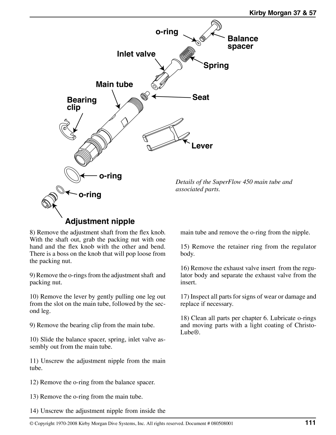
Details of the SuperFlow 450 main tube and associated parts.
main tube and remove the
15)Remove the retainer ring from the regulator body.
16)Remove the exhaust valve insert from the regu- lator body and separate the exhaust valve from the insert.
17)Inspect all parts for signs of wear or damage and replace if necessary.
18)Clean all parts per chapter 6. Lubricate
© Copyright | 111 |