Kirby Morgan 37 & 57
tube. The square opening on the main tube must be exposed.
19)Spread the arms of the lever just enough to install it on the main tube.
Inserting the inlet valve into the main tube.
20)Study the features of the inlet valve assembly. There are 4 “wings” towards one end of the assembly and a bore that creates the balance chamber on the opposite end.
The wings that align with the lever arm are the 2 that have an additional wall for the lever arm to bear on. The valve assembly should be inserted into the main tube with these walls toward the bottom of the regulator tube.
21)Using a clean wooden dowel rod, that has been sharpened in a pencil sharpener and inserted in the open end of the inlet valve, properly align and insert the inlet valve into the main tube. If this is done properly, the lever should lift up. If it does not, the valve has not been inserted correctly.
22)While holding the inlet valve in position, pull each arm of the lever outward just slightly until the inlet valves moves further into the main tube, ap- proximately 1/4 inch. The dowel rod should move in a bit further to indicate that this has happened.
23)Release your pressure on the dowel rod. The lever should fall back to its normal position against the main tube. Push in gently on the dowel and the lever
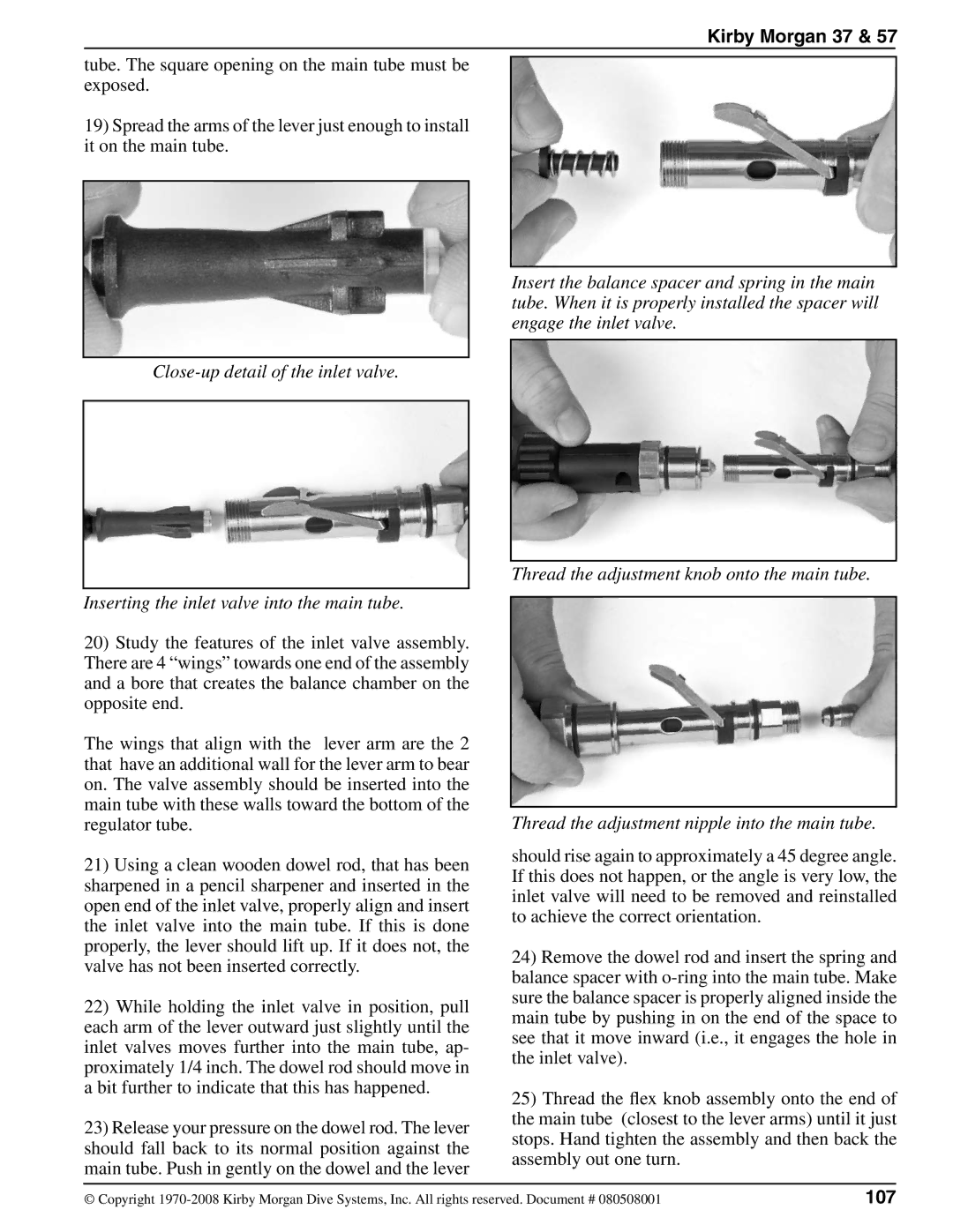
Insert the balance spacer and spring in the main tube. When it is properly installed the spacer will engage the inlet valve.
Thread the adjustment knob onto the main tube.
Thread the adjustment nipple into the main tube.
should rise again to approximately a 45 degree angle. If this does not happen, or the angle is very low, the inlet valve will need to be removed and reinstalled to achieve the correct orientation.
24)Remove the dowel rod and insert the spring and balance spacer with
25)Thread the flex knob assembly onto the end of the main tube (closest to the lever arms) until it just stops. Hand tighten the assembly and then back the assembly out one turn.
© Copyright | 107 |