Kirby Morgan 37 & 57
16)Install the
17)Fit the flattened end of the adjustment shaft into the flex knob.
18)Screw the adjustment shaft into the packing nut until it clicks.
19)Screw the packing nut and the entire flex knob assembly onto the main tube until it is hand tight.
Screw the flex knob assembly onto the main tube.
Screw the adjustment nipple into the open end of the main tube.
20)Screw the adjustment nipple into the main tube while watching for any movement of the lever (198). As soon as you see any movement of the lever, stop turning the nipple. Turn the nipple just enough so that the lever drops 1/8 inch.
21)Allow this assembly to sit for 24 hours so that the seat conforms to the adjustment nipple.
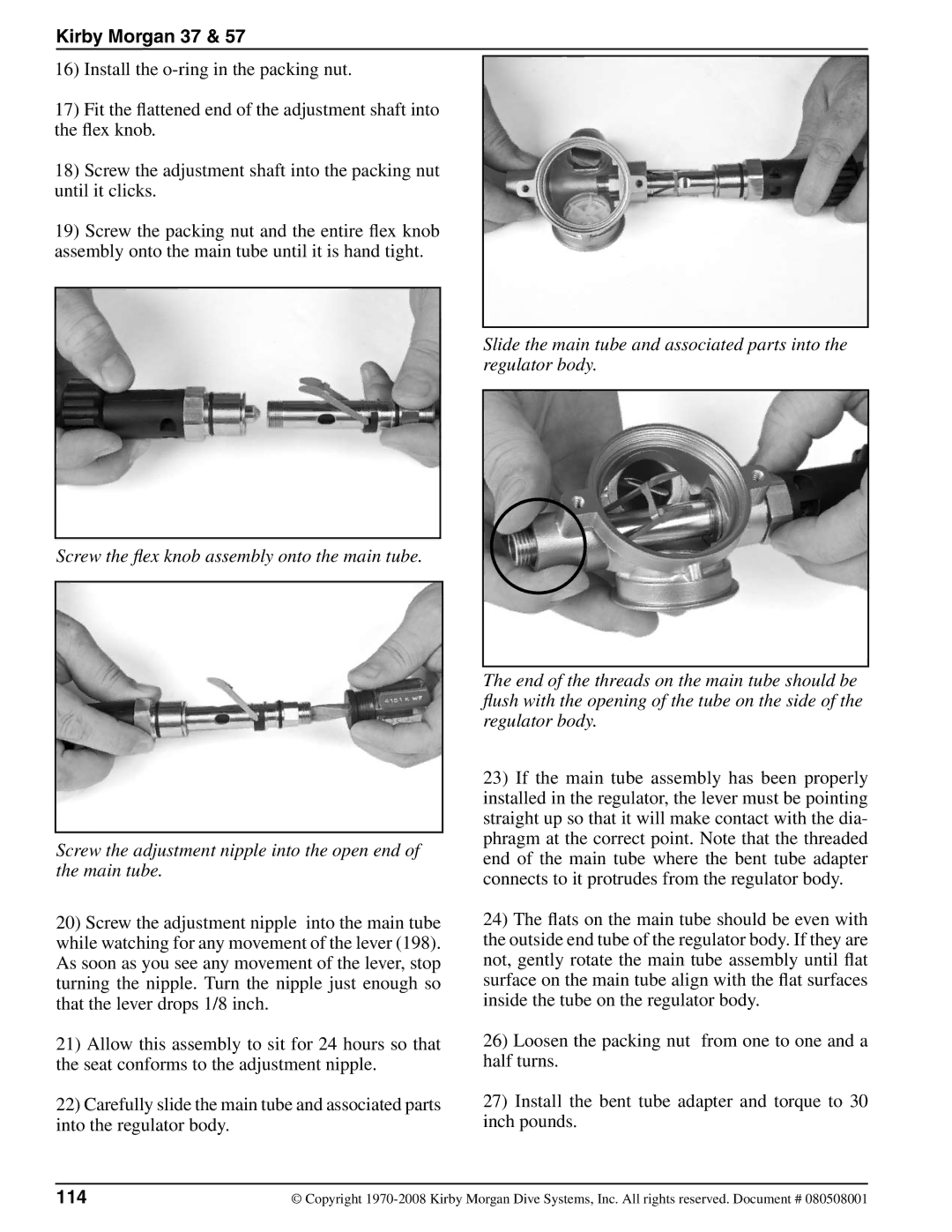
22)Carefully slide the main tube and associated parts into the regulator body.
Slide the main tube and associated parts into the regulator body.
The end of the threads on the main tube should be flush with the opening of the tube on the side of the regulator body.
23)If the main tube assembly has been properly installed in the regulator, the lever must be pointing straight up so that it will make contact with the dia- phragm at the correct point. Note that the threaded end of the main tube where the bent tube adapter connects to it protrudes from the regulator body.
24)The flats on the main tube should be even with the outside end tube of the regulator body. If they are not, gently rotate the main tube assembly until flat surface on the main tube align with the flat surfaces inside the tube on the regulator body.
26)Loosen the packing nut from one to one and a half turns.
27)Install the bent tube adapter and torque to 30 inch pounds.
114 | © Copyright |