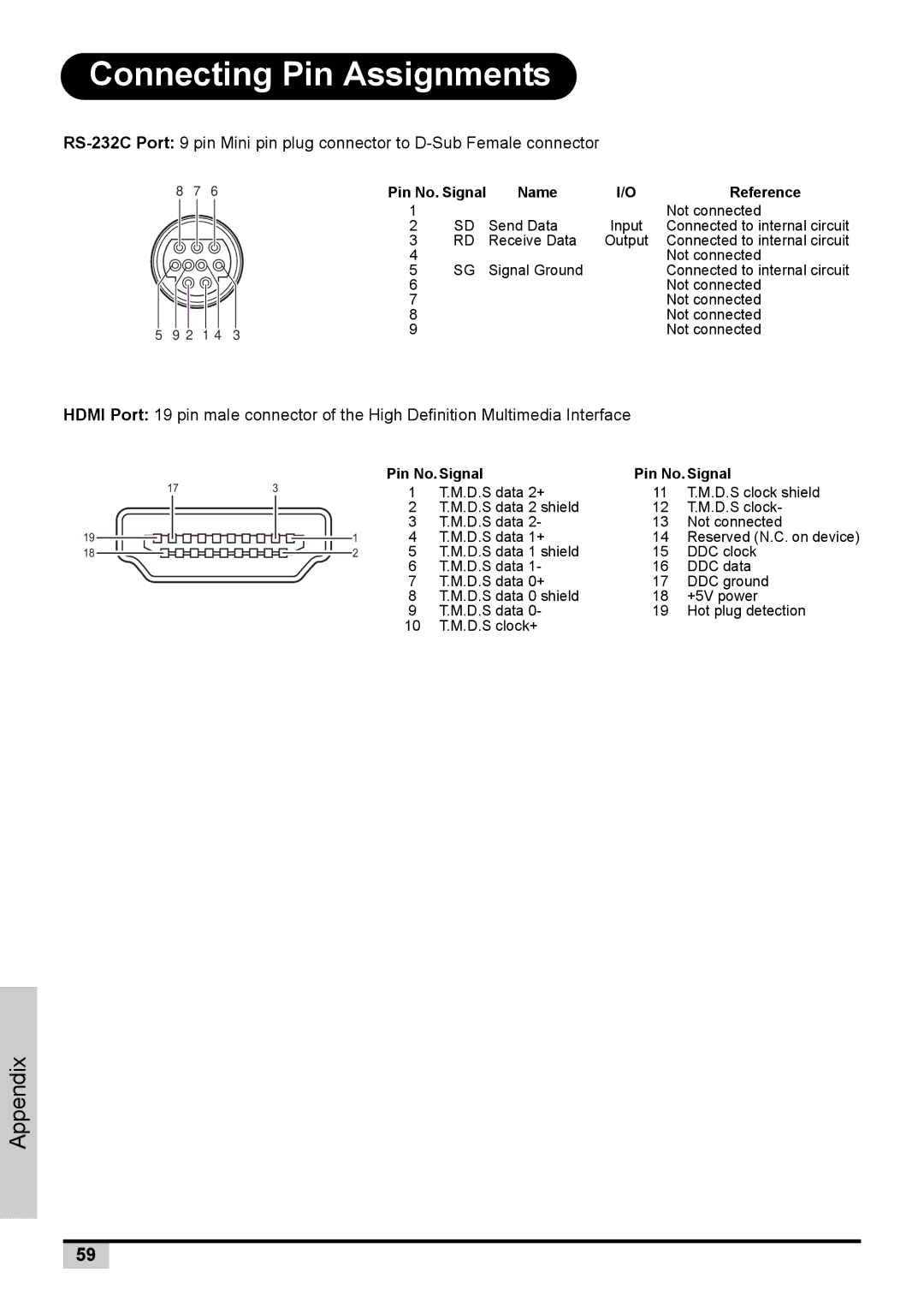
Connecting Pin Assignments
8 | 7 | 6 |
5 9 2 1 4 3
Pin No. Signal | Name | I/O | Reference | |
1 | SD | Send Data | Input | Not connected |
2 | Connected to internal circuit | |||
3 | RD | Receive Data | Output | Connected to internal circuit |
4 | SG | Signal Ground |
| Not connected |
5 |
| Connected to internal circuit | ||
6 |
|
|
| Not connected |
7 |
|
|
| Not connected |
8 |
|
|
| Not connected |
9 |
|
|
| Not connected |
HDMI Port: 19 pin male connector of the High Definition Multimedia Interface
17
19
18
|
|
|
|
|
|
|
|
|
|
| Pin No.Signal | Pin No.Signal | ||
3 |
|
|
|
|
|
|
|
|
|
| 1 | T.M.D.S data 2+ | 11 | T.M.D.S clock shield |
|
|
|
|
|
|
|
|
|
|
| 2 | T.M.D.S data 2 shield | 12 | T.M.D.S clock- |
|
|
|
|
|
|
|
|
|
|
| 3 | T.M.D.S data 2- | 13 | Not connected |
|
|
|
|
|
|
|
|
|
| 1 | 4 | T.M.D.S data 1+ | 14 | Reserved (N.C. on device) |
|
|
|
|
|
|
|
| 2 | 5 | T.M.D.S data 1 shield | 15 | DDC clock | ||
|
|
|
|
|
|
|
|
|
|
| 6 | T.M.D.S data 1- | 16 | DDC data |
|
|
|
|
|
|
|
|
|
|
| 7 | T.M.D.S data 0+ | 17 | DDC ground |
|
|
|
|
|
|
|
|
|
|
| 8 | T.M.D.S data 0 shield | 18 | +5V power |
|
|
|
|
|
|
|
|
|
|
| 9 | T.M.D.S data 0- | 19 | Hot plug detection |
|
|
|
|
|
|
|
|
|
|
| 10 | T.M.D.S clock+ |
|
|
Appendix
59
