Diagnostics
Malfunction |
| Check |
|
| |
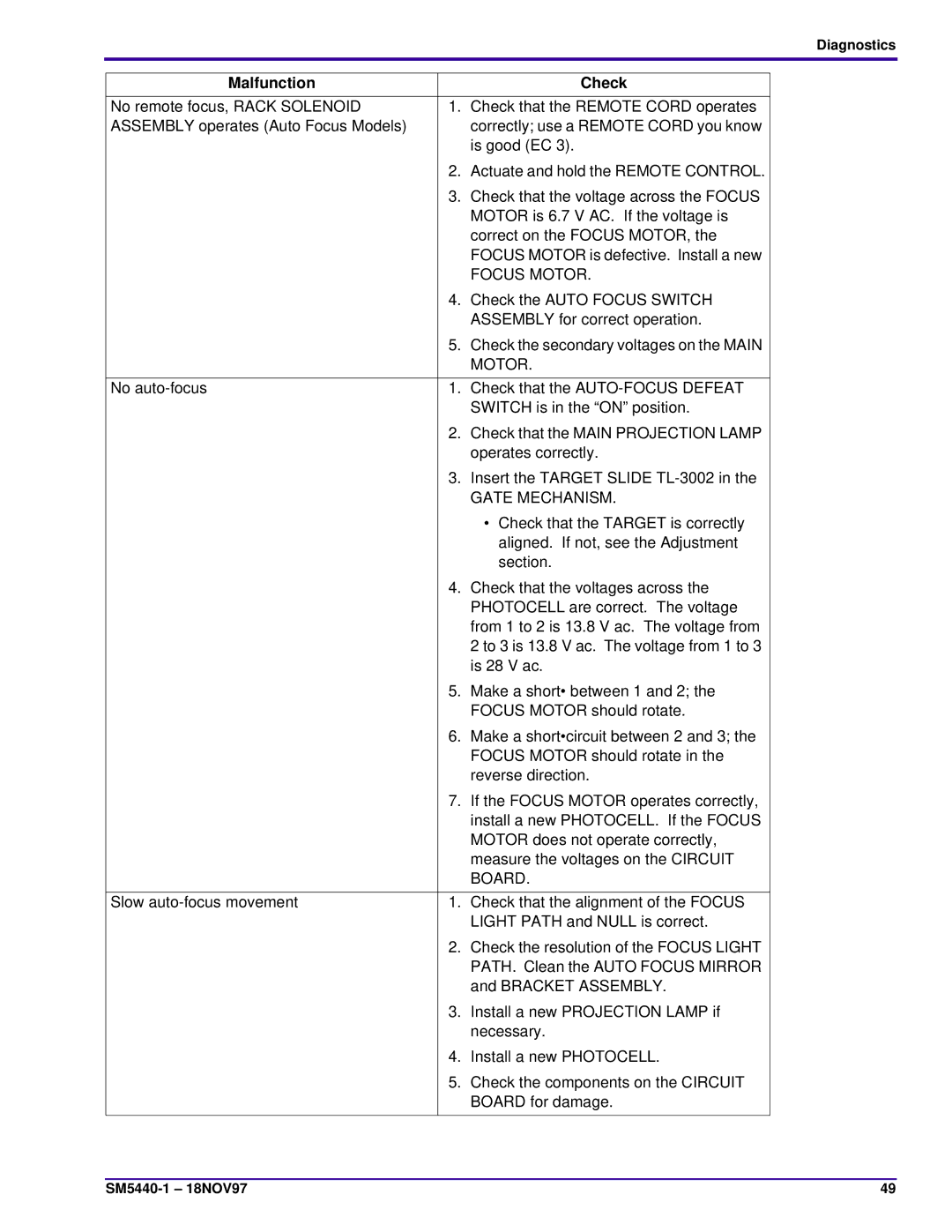
No remote focus, RACK SOLENOID | 1. Check that the REMOTE CORD operates | |
ASSEMBLY operates (Auto Focus Models) |
| correctly; use a REMOTE CORD you know |
|
| is good (EC 3). |
| 2. | Actuate and hold the REMOTE CONTROL. |
| 3. | Check that the voltage across the FOCUS |
|
| MOTOR is 6.7 V AC. If the voltage is |
|
| correct on the FOCUS MOTOR, the |
|
| FOCUS MOTOR is defective. Install a new |
|
| FOCUS MOTOR. |
| 4. | Check the AUTO FOCUS SWITCH |
|
| ASSEMBLY for correct operation. |
| 5. | Check the secondary voltages on the MAIN |
|
| MOTOR. |
|
| |
No | 1. Check that the | |
|
| SWITCH is in the “ON” position. |
| 2. | Check that the MAIN PROJECTION LAMP |
|
| operates correctly. |
| 3. | Insert the TARGET SLIDE |
|
| GATE MECHANISM. |
|
| • Check that the TARGET is correctly |
|
| aligned. If not, see the Adjustment |
|
| section. |
| 4. | Check that the voltages across the |
|
| PHOTOCELL are correct. The voltage |
|
| from 1 to 2 is 13.8 V ac. The voltage from |
|
| 2 to 3 is 13.8 V ac. The voltage from 1 to 3 |
|
| is 28 V ac. |
| 5. | Make a short• between 1 and 2; the |
|
| FOCUS MOTOR should rotate. |
| 6. | Make a short•circuit between 2 and 3; the |
|
| FOCUS MOTOR should rotate in the |
|
| reverse direction. |
| 7. | If the FOCUS MOTOR operates correctly, |
|
| install a new PHOTOCELL. If the FOCUS |
|
| MOTOR does not operate correctly, |
|
| measure the voltages on the CIRCUIT |
|
| BOARD. |
|
|
|
Slow | 1. | Check that the alignment of the FOCUS |
|
| LIGHT PATH and NULL is correct. |
| 2. | Check the resolution of the FOCUS LIGHT |
|
| PATH. Clean the AUTO FOCUS MIRROR |
|
| and BRACKET ASSEMBLY. |
| 3. | Install a new PROJECTION LAMP if |
|
| necessary. |
| 4. | Install a new PHOTOCELL. |
| 5. | Check the components on the CIRCUIT |
|
| BOARD for damage. |
|
|
|
49 |
