SERVICE MANUAL
Adjustment Specification
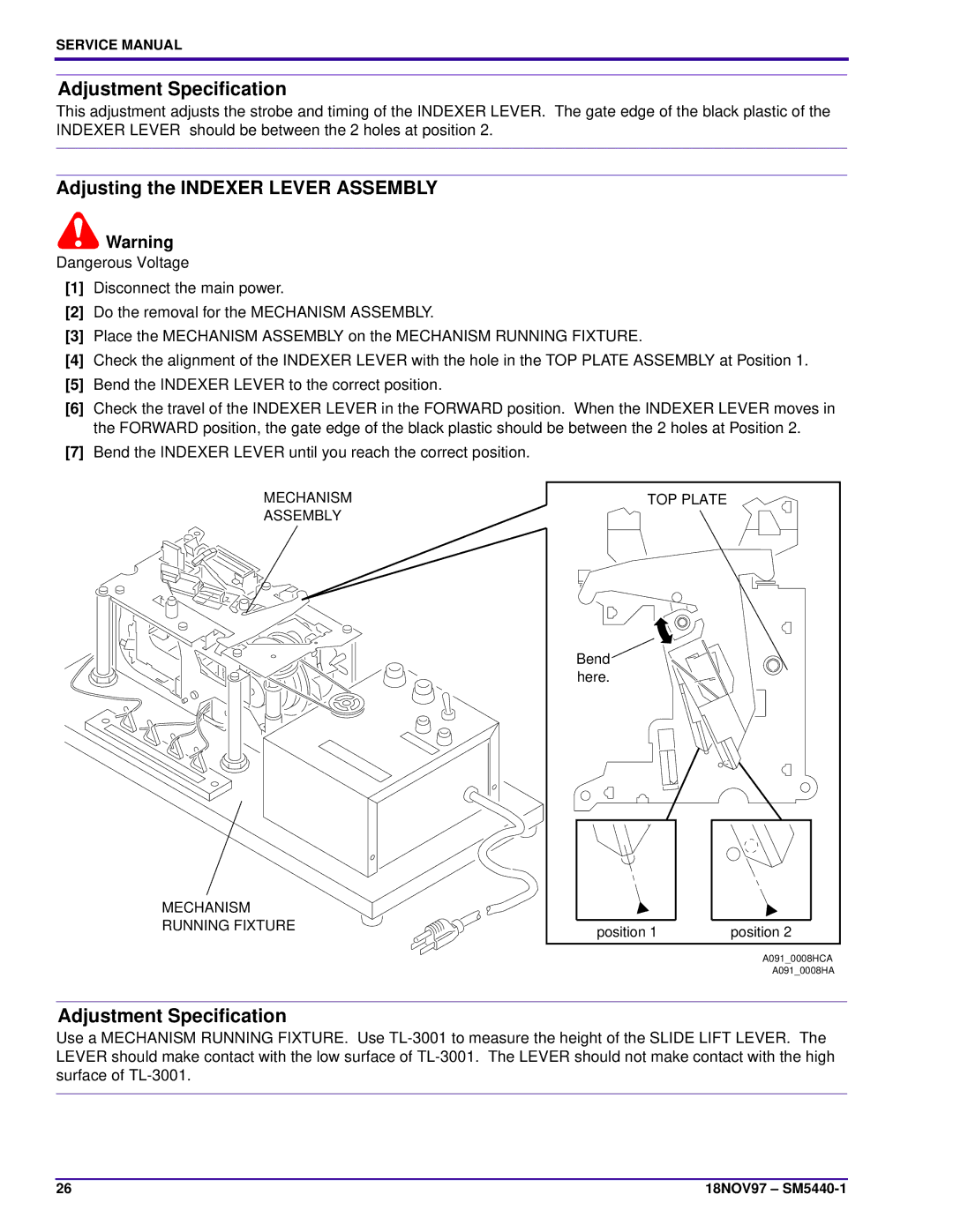
This adjustment adjusts the strobe and timing of the INDEXER LEVER. The gate edge of the black plastic of the INDEXER LEVER should be between the 2 holes at position 2.
Adjusting the INDEXER LEVER ASSEMBLY
![]() Warning
Warning
Dangerous Voltage
[1]Disconnect the main power.
[2]Do the removal for the MECHANISM ASSEMBLY.
[3]Place the MECHANISM ASSEMBLY on the MECHANISM RUNNING FIXTURE.
[4]Check the alignment of the INDEXER LEVER with the hole in the TOP PLATE ASSEMBLY at Position 1.
[5]Bend the INDEXER LEVER to the correct position.
[6]Check the travel of the INDEXER LEVER in the FORWARD position. When the INDEXER LEVER moves in the FORWARD position, the gate edge of the black plastic should be between the 2 holes at Position 2.
[7]Bend the INDEXER LEVER until you reach the correct position.
MECHANISM
ASSEMBLY
MECHANISM
RUNNING FIXTURE
TOP PLATE |
|
Bend |
|
here. |
|
position 1 | position 2 |
| A091_0008HCA |
| A091_0008HA |
Adjustment Specification
Use a MECHANISM RUNNING FIXTURE. Use
26 | 18NOV97 – |