SERVICE MANUAL
Replacing the AUTO-FOCUS BRACKET ASSEMBLY
![]() Warning
Warning
Dangerous Voltage
[1]Disconnect the main power.
[2]Do the replacement procedure for the LOWER HOUSING ASSEMBLY.
[3]Cut and remove the necessary WIRE TIES.
[4]Disconnect the 2 wires from the CYCLE SOLENOID on the SMALL CIRCUIT BOARD.
[5]Pull the SMALL CIRCUIT BOARD up.
[6]Do the replacement procedure for the MECHANISM ASSEMBLY.
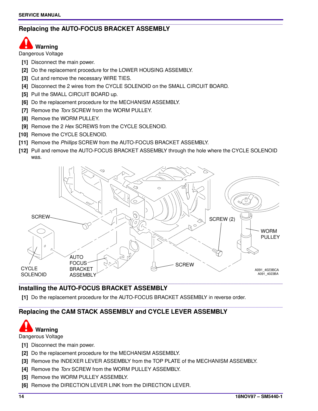
[7]Remove the Torx SCREW from the WORM PULLEY.
[8]Remove the WORM PULLEY.
[9]Remove the 2 Hex SCREWS from the CYCLE SOLENOID.
[10]Remove the CYCLE SOLENOID.
[11]Remove the Phillips SCREW from the
[12]Pull and remove the
SCREW | SCREW (2) |
|
WORM
PULLEY
AUTO
FOCUSSCREW
CYCLEBRACKET
SOLENOID ASSEMBLY
A091_4023BCA
A091_4023BA
Installing the AUTO-FOCUS BRACKET ASSEMBLY
[1]Do the replacement procedure for the
Replacing the CAM STACK ASSEMBLY and CYCLE LEVER ASSEMBLY
![]() Warning
Warning
Dangerous Voltage
[1]Disconnect the main power.
[2]Do the replacement procedure for the MECHANISM ASSEMBLY.
[3]Remove the INDEXER LEVER ASSEMBLY from the TOP PLATE of the MECHANISM ASSEMBLY.
[4]Remove the Torx SCREW from the WORM PULLEY ASSEMBLY.
[5]Remove the WORM PULLEY ASSEMBLY.
[6]Remove the DIRECTION LEVER LINK from the DIRECTION LEVER.
14 | 18NOV97 – |