Adjustments
Adjusting the SLIDE LIFT LEVER MANUAL, with MECHANISM Out
Warning
Dangerous Voltage
[1]Disconnect the main power.
[2]Do the removal for the MECHANISM ASSEMBLY.
[3]Place the MECHANISM ASSEMBLY on the MECHANISM RUNNING FIXTURE.
[4]Press and hold the SELECT LEVER down to move the SLIDE LIFT LEVER to the highest position.
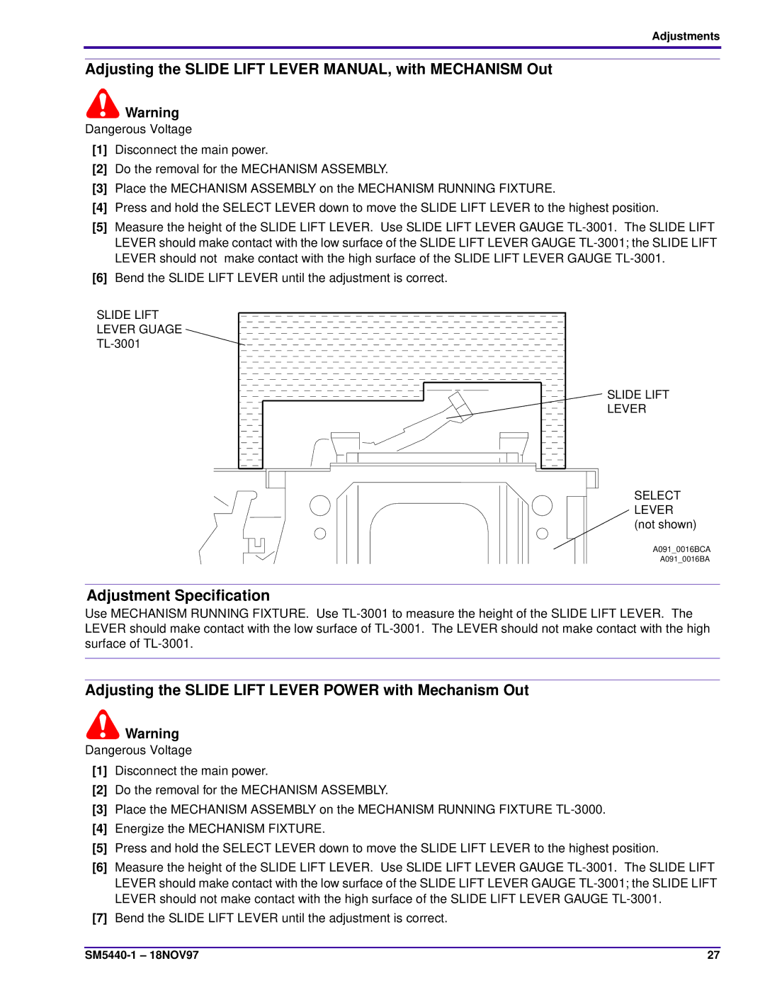
[5]Measure the height of the SLIDE LIFT LEVER. Use SLIDE LIFT LEVER GAUGE
[6]Bend the SLIDE LIFT LEVER until the adjustment is correct.
SLIDE LIFT LEVER GUAGE TL-3001
SLIDE LIFT |
LEVER |
SELECT
LEVER (not shown)
A091_0016BCA
A091_0016BA
Adjustment Specification
Use MECHANISM RUNNING FIXTURE. Use
Adjusting the SLIDE LIFT LEVER POWER with Mechanism Out
![]() Warning
Warning
Dangerous Voltage
[1]Disconnect the main power.
[2]Do the removal for the MECHANISM ASSEMBLY.
[3]Place the MECHANISM ASSEMBLY on the MECHANISM RUNNING FIXTURE
[4]Energize the MECHANISM FIXTURE.
[5]Press and hold the SELECT LEVER down to move the SLIDE LIFT LEVER to the highest position.
[6]Measure the height of the SLIDE LIFT LEVER. Use SLIDE LIFT LEVER GAUGE
[7]Bend the SLIDE LIFT LEVER until the adjustment is correct.
27 |
