Replacements and Installations
Replacing the MECHANISM ASSEMBLY
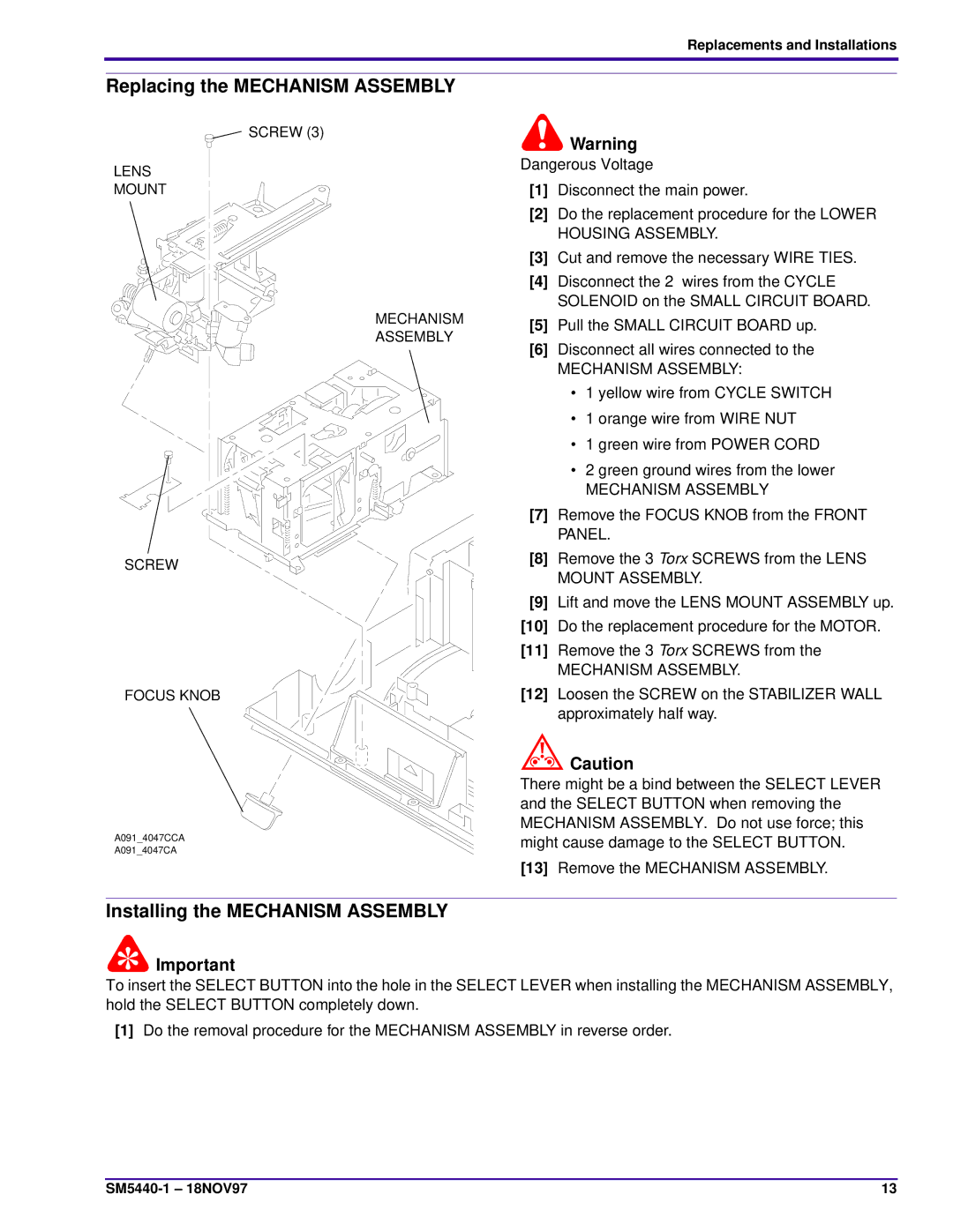
SCREW (3)
LENS
MOUNT
MECHANISM
ASSEMBLY
SCREW
FOCUS KNOB
A091_4047CCA
A091_4047CA
Warning
Dangerous Voltage
[1]Disconnect the main power.
[2]Do the replacement procedure for the LOWER HOUSING ASSEMBLY.
[3]Cut and remove the necessary WIRE TIES.
[4]Disconnect the 2 wires from the CYCLE SOLENOID on the SMALL CIRCUIT BOARD.
[5]Pull the SMALL CIRCUIT BOARD up.
[6]Disconnect all wires connected to the
MECHANISM ASSEMBLY:
•1 yellow wire from CYCLE SWITCH
•1 orange wire from WIRE NUT
•1 green wire from POWER CORD
•2 green ground wires from the lower
MECHANISM ASSEMBLY
[7]Remove the FOCUS KNOB from the FRONT PANEL.
[8]Remove the 3 Torx SCREWS from the LENS MOUNT ASSEMBLY.
[9]Lift and move the LENS MOUNT ASSEMBLY up.
[10]Do the replacement procedure for the MOTOR.
[11]Remove the 3 Torx SCREWS from the
MECHANISM ASSEMBLY.
[12]Loosen the SCREW on the STABILIZER WALL approximately half way.
![]() Caution
Caution
There might be a bind between the SELECT LEVER and the SELECT BUTTON when removing the MECHANISM ASSEMBLY. Do not use force; this might cause damage to the SELECT BUTTON.
[13]Remove the MECHANISM ASSEMBLY.
Installing the MECHANISM ASSEMBLY
![]() Important
Important
To insert the SELECT BUTTON into the hole in the SELECT LEVER when installing the MECHANISM ASSEMBLY, hold the SELECT BUTTON completely down.
[1]Do the removal procedure for the MECHANISM ASSEMBLY in reverse order.
13 |