Adjustments
[16]Set the projector to the
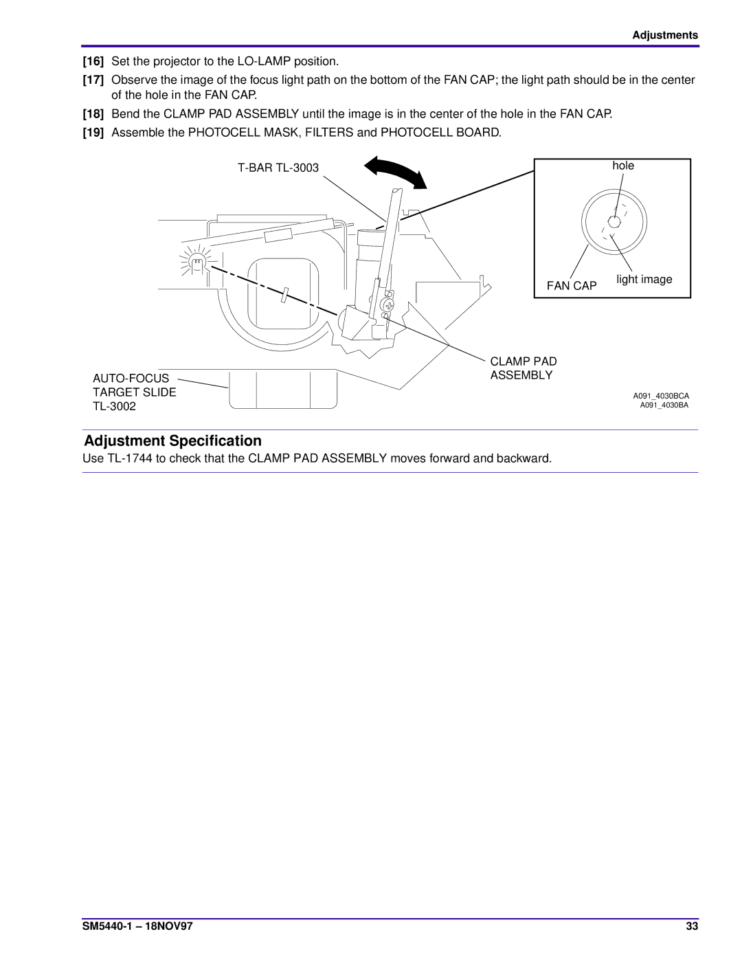
[17]Observe the image of the focus light path on the bottom of the FAN CAP; the light path should be in the center of the hole in the FAN CAP.
[18]Bend the CLAMP PAD ASSEMBLY until the image is in the center of the hole in the FAN CAP.
[19]Assemble the PHOTOCELL MASK, FILTERS and PHOTOCELL BOARD.
hole |
FAN CAP
light image
| CLAMP PAD |
| ASSEMBLY |
TARGET SLIDE | A091_4030BCA |
A091_4030BA |
Adjustment Specification
Use
33 |