|
| Your | ||
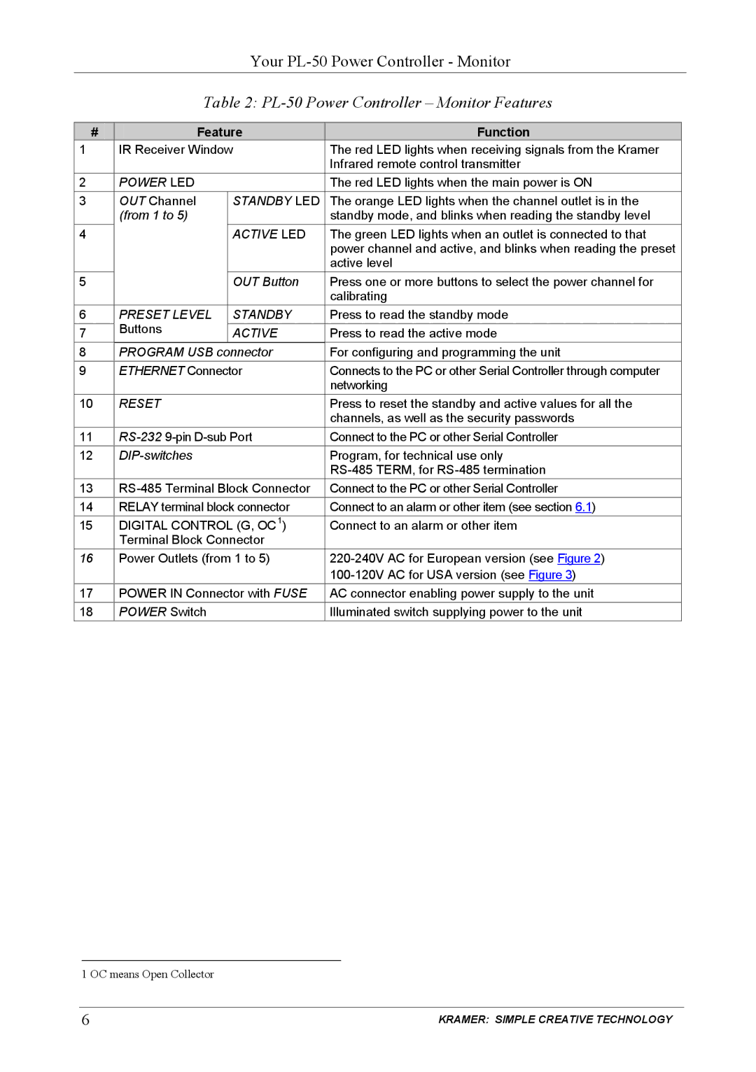
| Table 2: | |||
|
|
|
|
|
# | Feature | Function |
| |
1 | IR Receiver Window | The red LED lights when receiving signals from the Kramer |
| |
|
|
| Infrared remote control transmitter |
|
2 | POWER LED |
| The red LED lights when the main power is ON |
|
3 | OUT Channel | STANDBY LED | The orange LED lights when the channel outlet is in the |
|
| (from 1 to 5) |
| standby mode, and blinks when reading the standby level |
|
4 |
| ACTIVE LED | The green LED lights when an outlet is connected to that |
|
|
|
| power channel and active, and blinks when reading the preset |
|
|
|
| active level |
|
5 |
| OUT Button | Press one or more buttons to select the power channel for |
|
|
|
| calibrating |
|
6 | PRESET LEVEL | STANDBY | Press to read the standby mode |
|
7 | Buttons | ACTIVE | Press to read the active mode |
|
8 | PROGRAM USB connector | For configuring and programming the unit |
| |
9 | ETHERNET Connector | Connects to the PC or other Serial Controller through computer |
| |
|
|
| networking |
|
10 | RESET |
| Press to reset the standby and active values for all the |
|
|
|
| channels, as well as the security passwords |
|
11 | Connect to the PC or other Serial Controller |
| ||
12 |
|
| Program, for technical use only |
|
|
|
|
| |
13 | Connect to the PC or other Serial Controller |
| ||
14 | RELAY terminal block connector | Connect to an alarm or other item (see section 6.1) |
| |
15 | DIGITAL CONTROL (G, OC1) | Connect to an alarm or other item |
| |
| Terminal Block Connector |
|
| |
16 | Power Outlets (from 1 to 5) |
| ||
|
|
|
| |
17 | POWER IN Connector with FUSE | AC connector enabling power supply to the unit |
| |
18 | POWER Switch |
| Illuminated switch supplying power to the unit |
|
1 OC means Open Collector
6 | KRAMER: SIMPLE CREATIVE TECHNOLOGY |