Connecting the
6.3.5The Alerts Screen
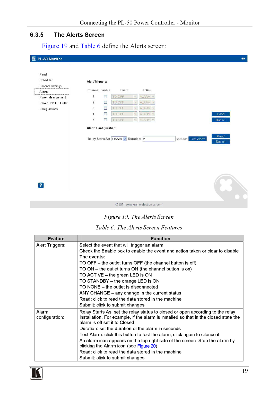
Figure 19 and Table 6 define the Alerts screen:
|
|
|
|
| Figure 19: The Alerts Screen | |
|
|
|
|
| Table 6: The Alerts Screen Features | |
|
|
|
|
|
|
|
|
|
|
| Feature | Function |
|
|
|
| Alert Triggers: | Select the event that will trigger an alarm: |
| |
|
|
|
|
| Check the Enable box to enable the event and action taken or clear to disable |
|
|
|
|
|
| The events: |
|
|
|
|
|
| TO OFF – the outlet turns OFF (the channel button is off) |
|
|
|
|
|
| TO ON – the outlet turns ON (the channel button is on) |
|
|
|
|
|
| TO ACTIVE – the green LED is ON |
|
|
|
|
|
| TO STANDBY – the orange LED is ON |
|
|
|
|
|
| TO NONE – the outlet is disconnected |
|
|
|
|
|
| ANY CHANGE – any change in the current status |
|
|
|
|
|
| Read: click to read the data stored in the machine |
|
|
|
|
|
| Submit: click to submit changes |
|
|
|
| Alarm | Relay Starts As: set the relay status to closed or open according to the relay |
| |
|
|
| configuration: | installation. For example, if the alarm is installed so that in the closed state the |
| |
|
|
|
|
| alarm is off set it to Closed |
|
|
|
|
|
| Duration: set the duration of the alarm in seconds |
|
|
|
|
|
| Test Alarm: click this button to test the alarm, click again to silence it |
|
|
|
|
|
| An alarm icon appears on the top right side of the screen. Stop the alarm by |
|
|
|
|
|
| clicking the Alarm icon (see Figure 20) |
|
|
|
|
|
| Read: click to read the data stored in the machine |
|
|
|
|
|
| Submit: click to submit changes |
|
|
|
|
|
|
|
|
|
|
|
|
| 19 | |
|
|
|
|
| ||
|
|
|
|
|
|
|
|
|
|
|
|
|
|