Connecting the
6.1Connecting the Relays
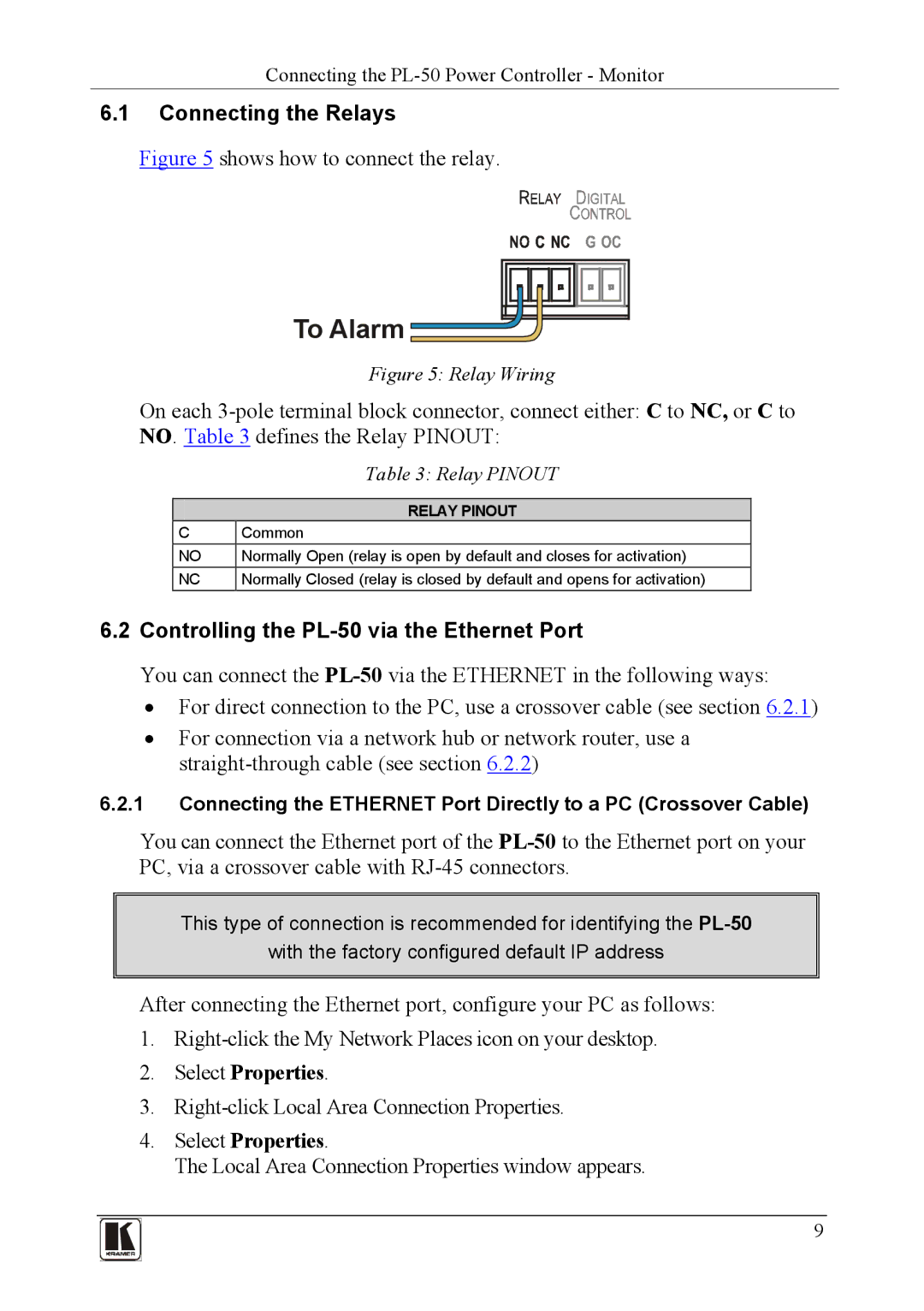
Figure 5 shows how to connect the relay.
To Alarm 
Figure 5: Relay Wiring
On each
| Table 3: Relay PINOUT |
|
|
| RELAY PINOUT |
C | Common |
NO | Normally Open (relay is open by default and closes for activation) |
NC | Normally Closed (relay is closed by default and opens for activation) |
6.2Controlling the PL-50 via the Ethernet Port
You can connect the
•For direct connection to the PC, use a crossover cable (see section 6.2.1)
•For connection via a network hub or network router, use a
6.2.1Connecting the ETHERNET Port Directly to a PC (Crossover Cable)
You can connect the Ethernet port of the
This type of connection is recommended for identifying the
with the factory configured default IP address
After connecting the Ethernet port, configure your PC as follows:
1.
2.Select Properties.
3.Right-click Local Area Connection Properties.
4.Select Properties.
The Local Area Connection Properties window appears.
9