8.5.3Ethernet Port Configuration and Control
Use the Kramer
Ethernet.
i
The latest version of
8.6Controlling the
The REMOTE terminal block connectors include:
∙A PIP pin and a G pin which are used for toggling between the Single and Dual window modes, and for selecting a PiP input
∙Nine input pins (defined in the table below) and a G pin for selecting an input
| PIN# |
|
|
| Input Source |
|
| PIN# |
|
| Input Source |
|
| PIN# |
|
| Input Source |
|
|
|
|
|
|
|
|
|
|
|
|
|
|
|
|
|
|
|
|
1 |
|
| HDMI 1 |
| 4 |
| PC 2 |
| 7 |
| CV 2 |
| ||||||
2 |
|
| HDMI 2 |
| 5 |
| COMP. |
| 8 |
| DP |
| ||||||
|
|
|
|
|
|
|
|
|
|
|
|
| ||||||
3 |
|
| PC 1 |
| 6 |
| CV 1 |
| 9 |
| N/A |
| ||||||
|
|
|
|
|
|
|
|
|
|
|
|
|
|
|
|
|
|
|
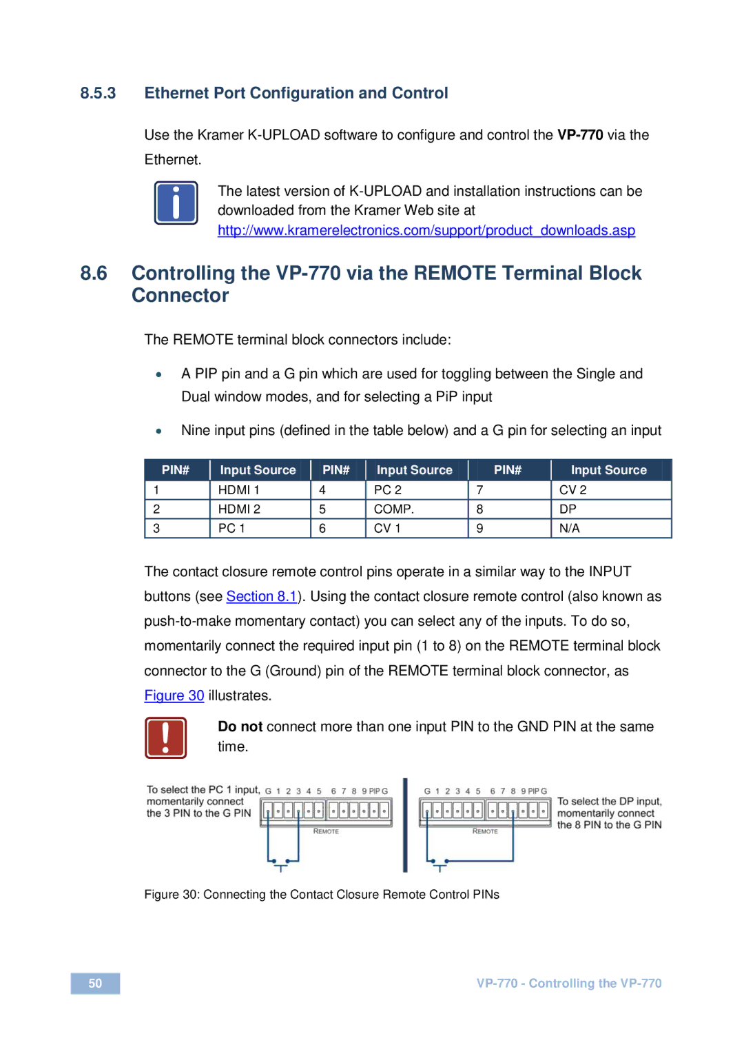
The contact closure remote control pins operate in a similar way to the INPUT buttons (see Section 8.1). Using the contact closure remote control (also known as
!Do not connect more than one input PIN to the GND PIN at the same time.
Figure 30: Connecting the Contact Closure Remote Control PINs
50 | |
|
|
