|
|
|
|
|
– Overview |
|
|
|
|
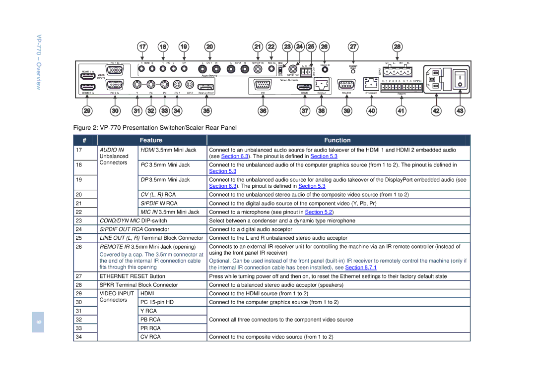
| Figure 2: | |||
| # |
| Feature | Function |
| 17 | AUDIO IN | HDMI 3.5mm Mini Jack | Connect to an unbalanced audio source for audio takeover of the HDMI 1 and HDMI 2 embedded audio |
|
| Unbalanced |
| (see Section 6.3). The pinout is defined in Section 5.3 |
| 18 | Connectors | PC 3.5mm Mini Jack | Connect to the unbalanced audio of the computer graphics source (from 1 to 2). The pinout is defined in |
|
| |||
|
|
|
| Section 5.3 |
| 19 |
| DP 3.5mm Mini Jack | Connect to the unbalanced audio source for analog audio takeover of the DisplayPort embedded audio (see |
|
|
|
| Section 6.3). The pinout is defined in Section 5.3 |
| 20 |
| CV (L, R) RCA | Connect to the unbalanced stereo audio of the composite video source (from 1 to 2) |
| 21 |
| S/PDIF IN RCA | Connect to the digital audio source of the component video (Y, Pb, Pr) |
| 22 |
| MIC IN 3.5mm Mini Jack | Connect to a microphone (see pinout in Section 5.2) |
| 23 | COND/DYN MIC | Select between a condenser and a dynamic type microphone | |
| 24 | S/PDIF OUT RCA Connector | Connect to a digital audio acceptor | |
| 25 | LINE OUT (L, R) Terminal Block Connector | Connect to the L and R unbalanced stereo audio acceptor | |
| 26 | REMOTE IR 3.5mm Mini Jack (opening) | Connects to an external IR receiver unit for controlling the machine via an IR remote controller (instead of | |
|
| Covered by a cap. The 3.5mm connector at | using the front panel IR receiver) | |
|
|
| ||
|
| the end of the internal IR connection cable | Optional. Can be used instead of the front panel | |
|
| fits through this opening | the internal IR connection cable has been installed), see Section 8.7.1 | |
| 27 | ETHERNET RESET Button | Press while turning power off and then on, to reset the Ethernet settings to their factory default state | |
| 28 | SPKR Terminal Block Connector | Connect to a balanced stereo audio acceptor (speakers) | |
| 29 | VIDEO INPUT | HDMI | Connect to the HDMI source (from 1 to 2) |
| 30 | Connectors | PC | Connect to the computer graphics source (from 1 to 2) |
|
| |||
| 31 |
| Y RCA |
|
9 | 32 |
| PB RCA | Connect all three connectors to the component video source |
|
|
|
| |
| 33 |
| PR RCA |
|
| 34 |
| CV RCA | Connect to the composite video source (from 1 to 2) |
