6.Operating the VibroCheck
12
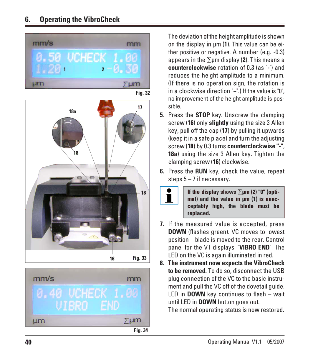
Fig. 32
17
18a
18
18
16 | Fig. 33 |
|
|
|
|
Fig. 34
The deviation of the height amplitude is shown on the display in μm (1). This value can be ei- ther positive or negative. A number (e.g.
5. Press the STOP key. Unscrew the clamping screw (16) only slightly using the size 3 Allen key, pull off the cap (17) by pulling it upwards (keep it in a safe place) and turn the adjusting screw (18) by 0.3 turns counterclockwise
6.Press the RUN key, check the value, repeat steps 5 – 7 if necessary.
If the display shows ∑μm (2) "0" (opti- mal) and the value in μm (1) is unac- ceptably high, the blade must be replaced.
7.If the measured value is accepted, press DOWN (flashes green). VC moves to lowest position – blade is moved to the rear. Control panel for the VT displays: "VIBRO END". The LED on the VC is again illuminated in red.
8.The instrument now expects the VibroCheck to be removed. To do so, disconnect the USB plug connection of the VC to the basic instru- ment and pull the VC off of the dovetail guide. LED in DOWN key continues to flash – wait until LED in DOWN button goes out.
The normal operating status is now restored.
40 | Operating Manual V1.1 – 05/2007 |