Electrical

ELECTROSTATIC DISCHARGE (ESD)

Precautions and Procedures

CAUTION

Electrostatic discharge can affect electronic com- ponents. Take precautions during furnace installa- tion and service to protect the furnace’s electronic controls. Precautions will help to avoid control ex- posure to electrostatic discharge by putting the fur- nace, the control and the technician at the same electrostatic potential. Neutralize electrostatic charge by touching hand and all tools on an un- painted unit surface, such as the gas valve or blower deck, before performing any service procedure.

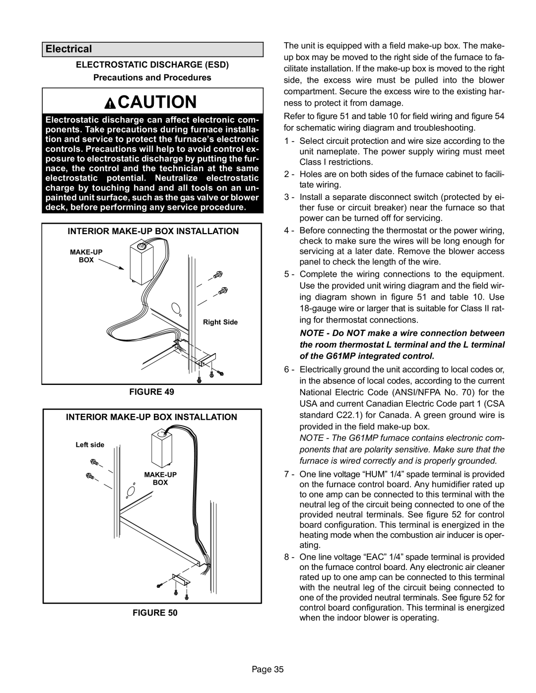
INTERIOR MAKE−UP BOX INSTALLATION

MAKE−UP

BOX

Right Side

FIGURE 49

INTERIOR MAKE−UP BOX INSTALLATION

Left side

MAKE−UP

BOX

FIGURE 50

The unit is equipped with a field make−up box. The make− up box may be moved to the right side of the furnace to fa- cilitate installation. If the make−up box is moved to the right side, the excess wire must be pulled into the blower compartment. Secure the excess wire to the existing har- ness to protect it from damage.

Refer to figure 51 and table 10 for field wiring and figure 54 for schematic wiring diagram and troubleshooting.

1 − Select circuit protection and wire size according to the unit nameplate. The power supply wiring must meet Class I restrictions.

2 − Holes are on both sides of the furnace cabinet to facili- tate wiring.

3 − Install a separate disconnect switch (protected by ei- ther fuse or circuit breaker) near the furnace so that power can be turned off for servicing.

4 − Before connecting the thermostat or the power wiring, check to make sure the wires will be long enough for servicing at a later date. Remove the blower access panel to check the length of the wire.

5 − Complete the wiring connections to the equipment. Use the provided unit wiring diagram and the field wir- ing diagram shown in figure 51 and table 10. Use 18−gauge wire or larger that is suitable for Class II rat- ing for thermostat connections.

NOTE − Do NOT make a wire connection between the room thermostat L terminal and the L terminal of the G61MP integrated control.

6 − Electrically ground the unit according to local codes or, in the absence of local codes, according to the current National Electric Code (ANSI/NFPA No. 70) for the USA and current Canadian Electric Code part 1 (CSA standard C22.1) for Canada. A green ground wire is provided in the field make−up box.

NOTE − The G61MP furnace contains electronic com- ponents that are polarity sensitive. Make sure that the furnace is wired correctly and is properly grounded.

7 − One line voltage ade terminal is provided

on the furnace control board. Any humidifier rated up to one amp can be connected to this terminal with the neutral leg of the circuit being connected to one of the provided neutral terminals. See figure 52 for control board configuration. This terminal is energized in the heating mode when the combustion air inducer is oper- ating.

8 − One line voltage 1/4" spade terminal is provided on the furnace control board. Any electronic air cleaner rated up to one amp can be connected to this terminal with the neutral leg of the circuit being connected to one of the provided neutral terminals. See figure 52 for control board configuration. This terminal is energized when the indoor blower is operating.

Page 35

Page 35
Image 35
Lennox International Inc G61MP Series Units, Gas Units Electrical, Electrostatic Discharge ESD, Precautions and Procedures

G61MP Series Units, Gas Units specifications

Lennox International Inc. has established itself as a leader in the heating and cooling industry, and its G61MP Series Gas Units stand as a testament to the company's commitment to innovation and energy efficiency. These gas units are specifically designed for residential applications and are recognized for their reliability, performance, and advanced technology.

One of the main features of the G61MP Series is its variable speed motor, which offers significantly enhanced comfort over traditional single-stage gas units. This technology allows for precise temperature control and improved humidity management. By adjusting its speed according to the heating demand, the unit minimizes temperature fluctuations, leading to a more consistent indoor climate.

Another notable characteristic of the G61MP Series is its ECM blower motor, which operates quietly and efficiently. This motor not only reduces energy consumption but also enhances the overall comfort of the home by providing a steady flow of warm air without the disruptive noise often associated with traditional gas units.

The G61MP Series units are designed with a focus on energy efficiency, boasting an impressive Annual Fuel Utilization Efficiency (AFUE) rating. This rating indicates that these units convert a significant portion of the fuel they consume into usable heat, resulting in lower energy bills for homeowners. The units are equipped with a modulating gas valve that further optimizes fuel usage by adjusting the gas flow according to the heating needs of the home.

Safety is a paramount consideration in the design of the G61MP Series. These units are built with advanced safety features, including a self-diagnostic control system that continuously monitors the unit’s performance. This system alerts homeowners to any potential issues, allowing for proactive maintenance and ensuring the longevity of the equipment.

The G61MP Series is also designed for ease of installation and servicing. Its compact design allows for flexible placement in various home environments, while the user-friendly access panels simplify routine maintenance tasks.

In conclusion, Lennox International Inc.'s G61MP Series Gas Units deliver a combination of advanced technology, energy efficiency, and reliability, making them an excellent choice for homeowners looking to enhance their heating systems. With features designed to maximize comfort, minimize energy costs, and ensure safety, these units represent a significant advancement in residential heating solutions.