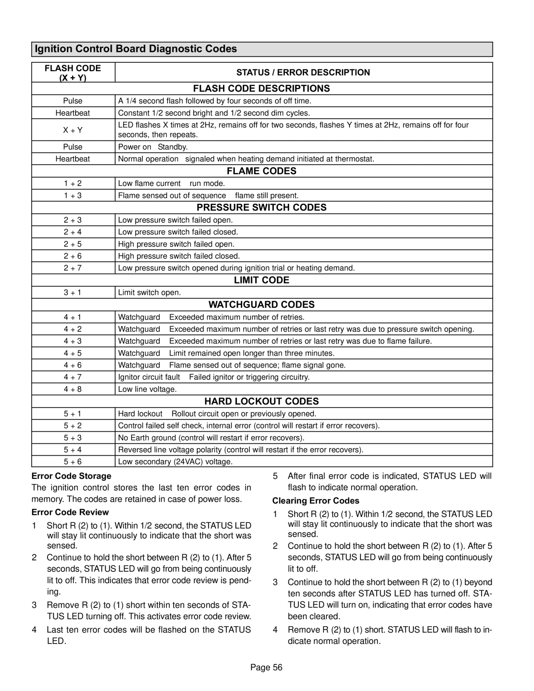
Ignition Control Board Diagnostic Codes

FLASH CODE

STATUS / ERROR DESCRIPTION

(X + Y)


FLASH CODE DESCRIPTIONS

Pulse

A 1/4 second flash followed by four seconds of off time.


Heartbeat

Constant 1/2 second bright and 1/2 second dim cycles.


X + Y

LED flashes X times at 2Hz, remains off for two seconds, flashes Y times at 2Hz, remains off for four

seconds, then repeats.


Pulse

Power on − Standby.


Heartbeat

Normal operation − signaled when heating demand initiated at thermostat.


FLAME CODES

1 + 2

Low flame current −− run mode.

1 + 3

Flame sensed out of sequence −− flame still present.


PRESSURE SWITCH CODES

2 + 3

Low pressure switch failed open.


2 + 4

Low pressure switch failed closed.


2 + 5

High pressure switch failed open.


2 + 6

High pressure switch failed closed.


2 + 7

Low pressure switch opened during ignition trial or heating demand.


LIMIT CODE

3 + 1

Limit switch open.


WATCHGUARD CODES

4 + 1

Watchguard −− Exceeded maximum number of retries.


4 + 2

Watchguard −− Exceeded maximum number of retries or last retry was due to pressure switch opening.


4 + 3

Watchguard −− Exceeded maximum number of retries or last retry was due to flame failure.


4 + 5

Watchguard −− Limit remained open longer than three minutes.


4 + 6

Watchguard −− Flame sensed out of sequence; flame signal gone.


4 + 7

Ignitor circuit fault −− Failed ignitor or triggering circuitry.


4 + 8

Low line voltage.


HARD LOCKOUT CODES

5 + 1

Hard lockout −− Rollout circuit open or previously opened.

5 + 2

Control failed self check, internal error (control will restart if error recovers).


5 + 3

No Earth ground (control will restart if error recovers).


5 + 4

Reversed line voltage polarity (control will restart if the error recovers).


5 + 6

Low secondary (24VAC) voltage.

Error Code Storage

The ignition control stores the last ten error codes in memory. The codes are retained in case of power loss.

Error Code Review

1 − Short R (2) to (1). Within 1/2 second, the STATUS LED will stay lit continuously to indicate that the short was sensed.

2 − Continue to hold the short between R (2) to (1). After 5 seconds, STATUS LED will go from being continuously lit to off. This indicates that error code review is pend- ing.

3 − Remove R (2) to (1) short within ten seconds of STA- TUS LED turning off. This activates error code review.

4 − Last ten error codes will be flashed on the STATUS LED.

5 − After final error code is indicated, STATUS LED will flash to indicate normal operation.

Clearing Error Codes

1 − Short R (2) to (1). Within 1/2 second, the STATUS LED will stay lit continuously to indicate that the short was sensed.

2 − Continue to hold the short between R (2) to (1). After 5 seconds, STATUS LED will go from being continuously lit to off.

3 − Continue to hold the short between R (2) to (1) beyond ten seconds after STATUS LED has turned off. STA- TUS LED will turn on, indicating that error codes have been cleared.

4 − Remove R (2) to (1) short. STATUS LED will flash to in- dicate normal operation.

Page 56

Page 56
Image 56
Lennox International Inc Gas Units Ignition Control Board Diagnostic Codes, Flash Code Status / Error Description, + Y

G61MP Series Units, Gas Units specifications

Lennox International Inc. has established itself as a leader in the heating and cooling industry, and its G61MP Series Gas Units stand as a testament to the company's commitment to innovation and energy efficiency. These gas units are specifically designed for residential applications and are recognized for their reliability, performance, and advanced technology.

One of the main features of the G61MP Series is its variable speed motor, which offers significantly enhanced comfort over traditional single-stage gas units. This technology allows for precise temperature control and improved humidity management. By adjusting its speed according to the heating demand, the unit minimizes temperature fluctuations, leading to a more consistent indoor climate.

Another notable characteristic of the G61MP Series is its ECM blower motor, which operates quietly and efficiently. This motor not only reduces energy consumption but also enhances the overall comfort of the home by providing a steady flow of warm air without the disruptive noise often associated with traditional gas units.

The G61MP Series units are designed with a focus on energy efficiency, boasting an impressive Annual Fuel Utilization Efficiency (AFUE) rating. This rating indicates that these units convert a significant portion of the fuel they consume into usable heat, resulting in lower energy bills for homeowners. The units are equipped with a modulating gas valve that further optimizes fuel usage by adjusting the gas flow according to the heating needs of the home.

Safety is a paramount consideration in the design of the G61MP Series. These units are built with advanced safety features, including a self-diagnostic control system that continuously monitors the unit’s performance. This system alerts homeowners to any potential issues, allowing for proactive maintenance and ensuring the longevity of the equipment.

The G61MP Series is also designed for ease of installation and servicing. Its compact design allows for flexible placement in various home environments, while the user-friendly access panels simplify routine maintenance tasks.

In conclusion, Lennox International Inc.'s G61MP Series Gas Units deliver a combination of advanced technology, energy efficiency, and reliability, making them an excellent choice for homeowners looking to enhance their heating systems. With features designed to maximize comfort, minimize energy costs, and ensure safety, these units represent a significant advancement in residential heating solutions.