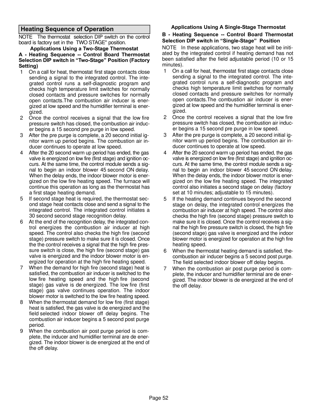
Heating Sequence of Operation

NOTE − The thermostat selection DIP switch on the control board is factory−set in the −STAGE" position.

Applications Using a Two−Stage Thermostat

A − Heating Sequence −− Control Board Thermostat Selection DIP switch in T wo−Stage" Position (Factory Setting)

1 − On a call for heat, thermostat first−stage contacts close sending a signal to the integrated control. The inte- grated control runs a self-diagnostic program and checks high temperature limit switches for normally closed contacts and pressure switches for normally open contacts.The combustion air inducer is ener- gized at low speed and the humidifier terminal is ener- gized.

2 − Once the control receives a signal that the low−fire pressure switch has closed, the combustion air induc- er begins a 15−second pre−purge in low speed.

3 − After the pre−purge is complete, a 20−second initial ig- nitor warm−up period begins. The combustion air in- ducer continues to operate at low speed.

4 − After the 20−second warm−up period has ended, the gas valve is energized on low fire (first stage) and ignition oc- curs. At the same time, the control module sends a sig- nal to begin an indoor blower 45−second ON−delay. When the delay ends, the indoor blower motor is ener- gized on the low fire heating speed. The furnace will continue this operation as long as the thermostat has a first−stage heating demand.

5 − If second−stage heat is required, the thermostat sec- ond−stage heat contacts close and send a signal to the integrated control. The integrated control initiates a 30−second second−stage recognition delay.

6 − At the end of the recognition delay, the integrated con- trol energizes the combustion air inducer at high speed. The control also checks the high−fire (second stage) pressure switch to make sure it is closed. Once the the control receives a signal that the high−fire pres- sure switch is close, the high−fire (second stage) gas valve is energized and the indoor blower motor is en- ergized for operation at the high−fire heating speed.

7 − When the demand for high−fire (second stage) heat is satisfied, the combustion air inducer is switched to the low−fire heating speed and the high−fire (second stage) gas valve is de−energized. The low−fire (first stage) gas valve continues operation. The indoor blower motor is switched to the low−fire heating speed.

8 − When the thermostat demand for low−fire (first stage) heat is satisfied, the gas valve is de−energized and the field−selected indoor blower off delay begins. The combustion air inducer begins a 5−second post−purge period.

9 − When the combustion air post−purge period is com- plete, the inducer and humidifier terminal are de−ener- gized. The indoor blower is de−energized at the end of the off delay.

Applications Using A Single−Stage Thermostat

B − Heating Sequence −− Control Board Thermostat Selection DIP switch in tage" Position

NOTE − In these applications, two−stage heat will be initi- ated by the integrated control if heating demand has not been satisfied after the field adjustable period (10 or 15 minutes).

1 − On a call for heat, thermostat first−stage contacts close sending a signal to the integrated control. The inte- grated control runs a self-diagnostic program and checks high temperature limit switches for normally closed contacts and pressure switches for normally open contacts.The combustion air inducer is ener- gized at low speed and the humidifier terminal is ener- gized.

2 − Once the control receives a signal that the low−fire pressure switch has closed, the combustion air induc- er begins a 15−second pre−purge in low speed.

3 − After the pre−purge is complete, a 20−second initial ig- nitor warm−up period begins. The combustion air in- ducer continues to operate at low speed.

4 − After the 20−second warm−up period has ended, the gas valve is energized on low fire (first stage) and ignition oc- curs. At the same time, the control module sends a sig- nal to begin an indoor blower 45−second ON−delay. When the delay ends, the indoor blower motor is ener- gized on the low−fire heating speed. The integrated control also initiates a second−stage on delay (factory− set at 10 minutes; adjustable to 15 minutes).

5 − If the heating demand continues beyond the second− stage on delay, the integrated control energizes the combustion air inducer at high speed. The control also checks the high−fire (second stage) pressure switch to make sure it is closed. Once the control receives a sig- nal the high−fire pressure switch is closed, the high−fire (second stage) gas valve is energized and the indoor blower motor is energized for operation at the high−fire heating speed.

6 − When the thermostat heating demand is satisfied, the- combustion air inducer begins a 5−second post−purge. The field−selected indoor blower off delay begins.

7 − When the combustion air post−purge period is com- plete, the inducer and humidifier terminal are de−ener- gized. The indoor blower is de−energized at the end of the off delay.

Page 52

Page 52
Image 52
Lennox International Inc Gas Units, G61MP Series Units installation instructions Heating Sequence of Operation

G61MP Series Units, Gas Units specifications

Lennox International Inc. has established itself as a leader in the heating and cooling industry, and its G61MP Series Gas Units stand as a testament to the company's commitment to innovation and energy efficiency. These gas units are specifically designed for residential applications and are recognized for their reliability, performance, and advanced technology.

One of the main features of the G61MP Series is its variable speed motor, which offers significantly enhanced comfort over traditional single-stage gas units. This technology allows for precise temperature control and improved humidity management. By adjusting its speed according to the heating demand, the unit minimizes temperature fluctuations, leading to a more consistent indoor climate.

Another notable characteristic of the G61MP Series is its ECM blower motor, which operates quietly and efficiently. This motor not only reduces energy consumption but also enhances the overall comfort of the home by providing a steady flow of warm air without the disruptive noise often associated with traditional gas units.

The G61MP Series units are designed with a focus on energy efficiency, boasting an impressive Annual Fuel Utilization Efficiency (AFUE) rating. This rating indicates that these units convert a significant portion of the fuel they consume into usable heat, resulting in lower energy bills for homeowners. The units are equipped with a modulating gas valve that further optimizes fuel usage by adjusting the gas flow according to the heating needs of the home.

Safety is a paramount consideration in the design of the G61MP Series. These units are built with advanced safety features, including a self-diagnostic control system that continuously monitors the unit’s performance. This system alerts homeowners to any potential issues, allowing for proactive maintenance and ensuring the longevity of the equipment.

The G61MP Series is also designed for ease of installation and servicing. Its compact design allows for flexible placement in various home environments, while the user-friendly access panels simplify routine maintenance tasks.

In conclusion, Lennox International Inc.'s G61MP Series Gas Units deliver a combination of advanced technology, energy efficiency, and reliability, making them an excellent choice for homeowners looking to enhance their heating systems. With features designed to maximize comfort, minimize energy costs, and ensure safety, these units represent a significant advancement in residential heating solutions.