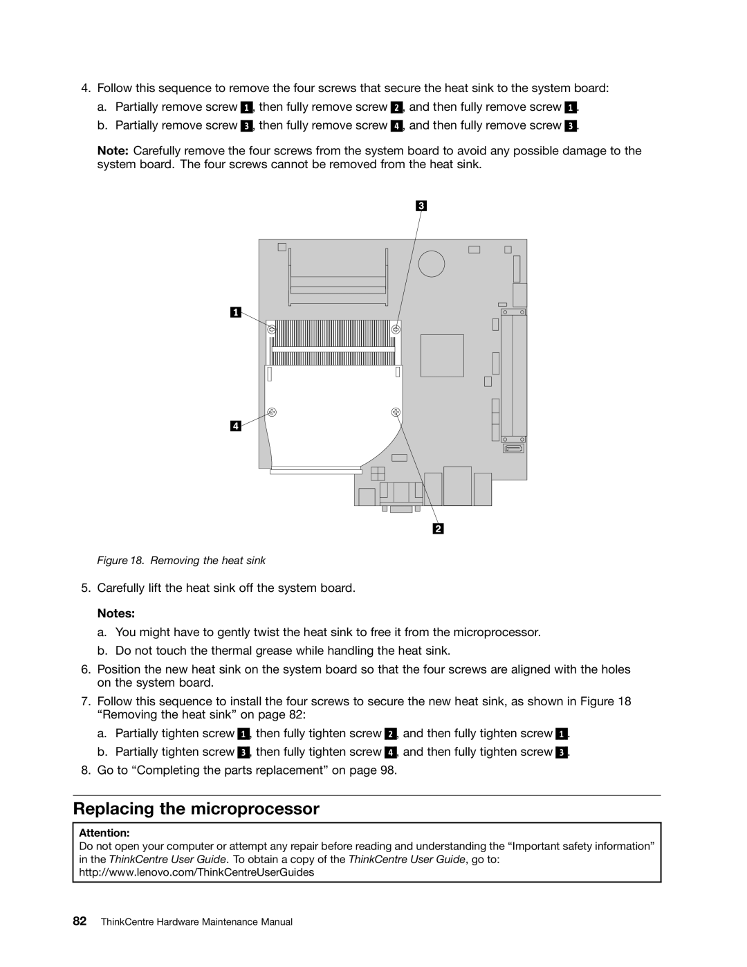
4.Follow this sequence to remove the four screws that secure the heat sink to the system board:
a.Partially remove screw 1 , then fully remove screw 2 , and then fully remove screw 1 .
b.Partially remove screw 3 , then fully remove screw 4 , and then fully remove screw 3 .
Note: Carefully remove the four screws from the system board to avoid any possible damage to the system board. The four screws cannot be removed from the heat sink.
Figure 18. Removing the heat sink
5.Carefully lift the heat sink off the system board.
Notes:
a.You might have to gently twist the heat sink to free it from the microprocessor.
b.Do not touch the thermal grease while handling the heat sink.
6.Position the new heat sink on the system board so that the four screws are aligned with the holes on the system board.
7.Follow this sequence to install the four screws to secure the new heat sink, as shown in Figure 18 “Removing the heat sink” on page 82:
a.Partially tighten screw 1 , then fully tighten screw 2 , and then fully tighten screw
b.Partially tighten screw 3 , then fully tighten screw 4 , and then fully tighten screw
8.Go to “Completing the parts replacement” on page 98.
1.
3.
Replacing the microprocessor
Attention:
Do not open your computer or attempt any repair before reading and understanding the “Important safety information” in the ThinkCentre User Guide. To obtain a copy of the ThinkCentre User Guide, go to: http://www.lenovo.com/ThinkCentreUserGuides