Installation
USB External device | LAN connection |
13
Connect the external device to the USB port. (Example: External HDD or other external storage.)
Mouse
Connect the USB mouse to operate the system.
Connecting E-SATA device
You can use
|
|
| |||
| 2 |
| 4 |
|
|
ARM |
|
|
|
|
|
OUT |
|
| USB | DC 48 V | |
|
| 5 V | 0.5 A |
| |
1 2 G |
|
|
| ||
|
|
|
|
| |
LAN | 1 | CAM | 3 |
| |
Connecting Network
You can control and monitor the system via network. With the remote control (monitoring), you can change the system configuration or monitor the image via network. After the installation, check the network settings for the remote control and monitoring work.
Network connection |
|
|
|
| ||
485 | IN | OUT |
|
| 5 V | 0.5 A |
- + 1 2 3 4 G 1 2 G |
|
| ||||
|
|
|
| |||
|
| LAN | 1 | CAM | 3 | |
|
|
|
| Router |
| Broadband |
|
|
|
|
| Service | |
|
|
|
|
|
| |
Connect the LAN port to an available 10/100/1000
IP Camera connection
Connect the IP camera. After the installation, check the IP camera settings on the setup menu.
Automatic network configuration
The system can automatically obtain and configure the network interface via DHCP.
Manually configure network
The system may be manually configured by assigning an IP address, subnet mask, gateway and DNS.
![]() NOTE
NOTE
This unit can be supported IPv4 and IPv6 network.
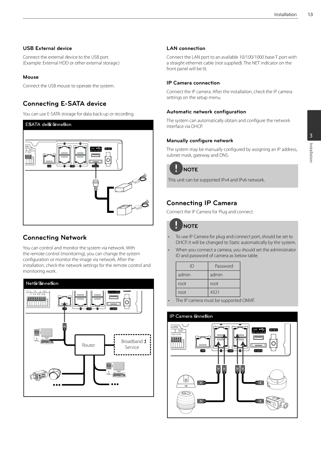
Connecting IP Camera
Connect the IP Camera for Plug and connect.
![]() NOTE
NOTE
•To use IP Camera for plug and connect port, should be set to DHCP. It will be changed to Static automatically by the system.
•When you connect a camera, you should set the administrator ID and password of camera as below table.
ID | Password |
|
|
admin | admin |
|
|
root | root |
|
|
root | 4321 |
|
|
•The IP camera must be supported ONVIF.
IP Camera connection |
|
|
|
|
|
| 2 |
| 4 |
|
|
ALARM |
|
|
|
|
|
OUT |
|
| USB | DC 48 V | |
|
| 5 V | 0.5 A |
| |
4 G 1 2 G |
|
|
| ||
|
|
|
|
| |
LAN | 1 | CAM | 3 |
| |
3
Installation