14Installation
Connecting LKD1000 Controller
This system has a data terminal. Use this port to connect keyboard (optional).
Description | |
|
|
- (DATA | Data Transmission/Reception |
|
|
+ (DATA +) | Data Transmission/Reception |
|
|
GND | Shield |
|
|
Connect the LKD1000 controller to control the system. (Refer to the manuals of the LKD1000 controller for more details.)
3 | LKD1000 controller connection |
|
|
| ||||
|
|
|
|
|
|
|
| |
Installation |
|
|
|
|
| 2 |
| 4 |
|
| RS | ALARM |
|
|
| ||
|
|
|
|
|
| US | ||
|
| 485 | IN | OUT |
|
| ||
|
|
|
| 5 V | ||||
|
| - + 1 2 3 4 G 1 2 G |
|
| ||||
|
|
|
|
| ||||
|
|
|
|
|
|
|
| |
| VGA | HDMI |
|
| LAN | 1 | CAM | 3 |
|
| RS |
|
| ALARM |
|
|
|
|
|
|
|
|
|
|
| |
|
| 485 |
| IN | OUT |
|
|
|
|
| - + 1 2 3 4 G 1 2 G |
|
|
| |||
|
| TX- | TX+ |
|
|
|
|
|
|
|
|
|
| Controller LKD1000 |
| ||
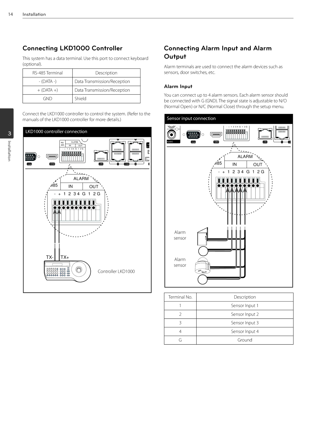
Connecting Alarm Input and Alarm Output
Alarm terminals are used to connect the alarm devices such as sensors, door switches, etc.
Alarm Input
You can connect up to 4 alarm sensors. Each alarm sensor should be connected with G (GND). The signal state is adjustable to N/O (Normal Open) or N/C (Normal Close) through the setup menu.
Sensor input connection |
|
|
|
| ||
|
|
| - + 1 2 3 4 G 1 2 G |
|
|
|
AUDIO | VGA | HDMI |
| LAN | 1 | CA |
|
| RS | ALARM |
|
|
|
|
|
|
|
|
| |
|
| 485 | IN | OUT |
|
|
|
| - + 1 2 3 4 G 1 2 G |
|
| ||
| Alarm |
|
|
|
|
|
| sensor |
|
|
|
|
|
| Alarm |
|
|
|
|
|
| sensor |
|
|
|
|
|
Terminal No. | Description |
|
|
1 | Sensor Input 1 |
|
|
2 | Sensor Input 2 |
|
|
3 | Sensor Input 3 |
|
|
4 | Sensor Input 4 |
|
|
G | Ground |
|
|