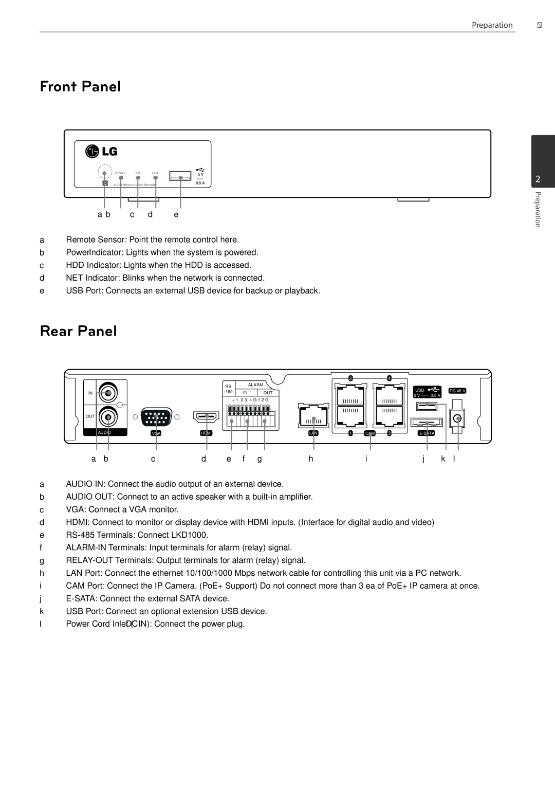
Front Panel
POWER HDD LAN
H.264 Network Video Recorder
A B C D E
ARemote Sensor: Point the remote control here.
BPower Indicator: Lights when the system is powered.
CHDD Indicator: Lights when the HDD is accessed.
DNET Indicator: Blinks when the network is connected.
EUSB Port: Connects an external USB device for backup or playback.
Preparation 9
2
Preparation
Rear Panel
|
|
| RS |
| ALARM |
|
|
|
|
| |
IN |
|
| 485 | IN | OUT |
|
|
| - + 1 2 3 4 G 1 2 G | ||
OUT |
|
|
|
|
|
AUDIO | VGA | HDMI |
|
| LAN |
|
|
|
|
|
|
| 2 |
|
|
|
|
|
|
|
|
|
|
|
| 4 |
|
|
|
|
|
|
|
|
|
|
|
|
|
|
|
|
|
|
|
|
|
|
| |||
|
|
|
|
|
|
|
|
|
|
|
|
|
|
|
|
|
|
|
|
|
|
|
|
|
|
|
|
|
|
|
| USB |
|
| DC 48 V | |||||||||||
|
|
|
|
|
|
|
|
|
|
|
|
|
|
|
|
|
|
|
|
|
|
|
|
|
|
|
|
|
|
|
|
|
| |||||||||||||
|
|
|
|
|
|
|
|
|
|
|
|
|
|
|
|
|
|
|
|
|
|
|
|
|
|
|
|
|
| 5 V |
| 0.5 A |
|
|
|
|
|
| ||||||||
|
|
|
|
|
|
|
|
|
|
|
|
|
|
|
|
|
|
|
|
|
|
|
|
|
|
|
|
|
|
|
|
|
|
|
|
|
|
|
|
|
|
|
|
|
|
|
|
|
|
|
|
|
|
|
|
|
|
|
|
|
|
|
|
|
|
|
|
|
|
|
|
|
|
|
|
|
|
|
|
|
|
|
|
|
|
|
|
|
|
|
|
|
|
|
|
|
|
|
|
|
|
|
|
|
|
|
|
|
|
|
|
|
|
|
|
|
|
|
|
|
|
|
|
|
|
|
|
|
|
|
|
|
|
|
| |||||
|
|
|
|
|
|
|
|
|
|
|
|
|
|
|
|
|
|
|
|
|
|
|
|
|
|
|
|
|
|
|
|
|
|
|
|
|
|
|
|
|
|
|
|
|
|
|
|
|
|
|
|
|
| 1 |
|
|
|
| CAM | 3 |
|
|
|
|
|
|
|
|
|
|
|
|
|
|
|
| |||||||||||||||||
|
|
|
|
|
|
|
|
|
|
|
|
|
|
|
|
|
|
|
|
|
|
|
|
|
|
| ||||||||||||||||||||
|
|
|
|
|
|
|
|
|
|
|
|
|
|
|
|
|
|
|
|
|
|
|
|
|
|
|
|
|
|
|
|
|
|
|
|
|
|
|
|
|
|
|
|
|
|
|
A B C D E F G H I J K L
AAUDIO IN: Connect the audio output of an external device.
BAUDIO OUT: Connect to an active speaker with a
CVGA: Connect a VGA monitor.
DHDMI: Connect to monitor or display device with HDMI inputs. (Interface for digital audio and video)
E
F
G
HLAN Port: Connect the ethernet 10/100/1000 Mbps network cable for controlling this unit via a PC network.
ICAM Port: Connect the IP Camera. (PoE+ Support) Do not connect more than 3 ea of PoE+ IP camera at once.
J
KUSB Port: Connect an optional extension USB device.
LPower Cord Inlet (DC IN): Connect the power plug.