OPERATION | ||
|
|
|
WIRE REEL LOADING – 50 AND 60 LB COILS (K303 OR K376 WIRE REEL STAND)
ADJUSTABLE WIRE REEL BRAKE
The mount for standard 50 and 60 pound electrode coils includes a
To adjust the brake position, remove the wire reel. Pull the cotter pin that holds the brake shoe to the arm, move the shoe and replace the cotter pin. Do not bend the cotter pin - it is held in place by a friction fit.
TO MOUNT A 50 OR 60 LB COIL:
1. To remove the wire reel from its shaft, grasp the |
spring loaded knob and pull out. This straightens |
![]() CAUTION
CAUTION
Always be sure the free end of the coil is securely held while the tie wires are being cut and until the wire is feeding through the drive rolls. Failure to do this will result in “back lashing” of the coil, which may tangle the wire. A tangled coil will not feed. It must be untangled or discarded.
8.Cut and remove only the tie wire holding the free end of the coil. Insert the free end into one of the holes in the cover and secure it by bending it back. Cut and remove the remaining tie wires.
9.Replace the reel on the wire feeder. Grasp the shaft knob, pull it out and swing it across the reel hub, locking the reel in place.
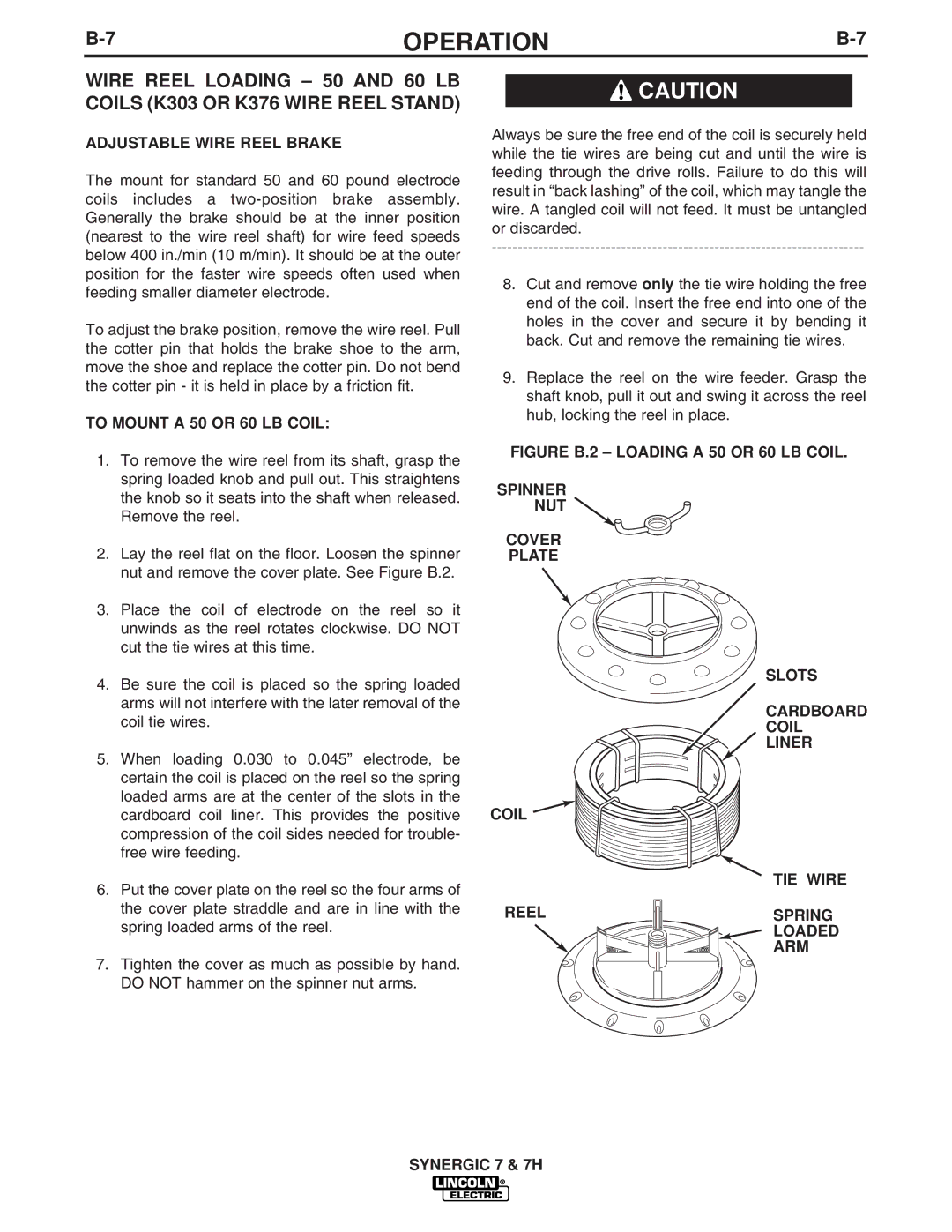
FIGURE B.2 – LOADING A 50 OR 60 LB COIL.
| the knob so it seats into the shaft when released. |
| Remove the reel. |
2. | Lay the reel flat on the floor. Loosen the spinner |
| nut and remove the cover plate. See Figure B.2. |
3. | Place the coil of electrode on the reel so it |
| unwinds as the reel rotates clockwise. DO NOT |
| cut the tie wires at this time. |
4. | Be sure the coil is placed so the spring loaded |
| arms will not interfere with the later removal of the |
| coil tie wires. |
5. | When loading 0.030 to 0.045” electrode, be |
| certain the coil is placed on the reel so the spring |
| loaded arms are at the center of the slots in the |
| cardboard coil liner. This provides the positive |
| compression of the coil sides needed for trouble- |
| free wire feeding. |
6. | Put the cover plate on the reel so the four arms of |
| the cover plate straddle and are in line with the |
| spring loaded arms of the reel. |
7. Tighten the cover as much as possible by hand. | |
| DO NOT hammer on the spinner nut arms. |
SPINNER
NUT ![]()
COVER
PLATE
COIL
REEL
SLOTS
CARDBOARD COIL LINER
TIE WIRE
SPRING
LOADED
ARM
SYNERGIC 7 & 7H