TROUBLESHOOTING | ||
|
|
|
| Observe all Safety Guidelines detailed throughout this manual |
|
|
|
|
PROBLEMS
(SYMPTOMS)
POSSIBLE
CAUSE
RECOMMENDED
COURSE OF ACTION
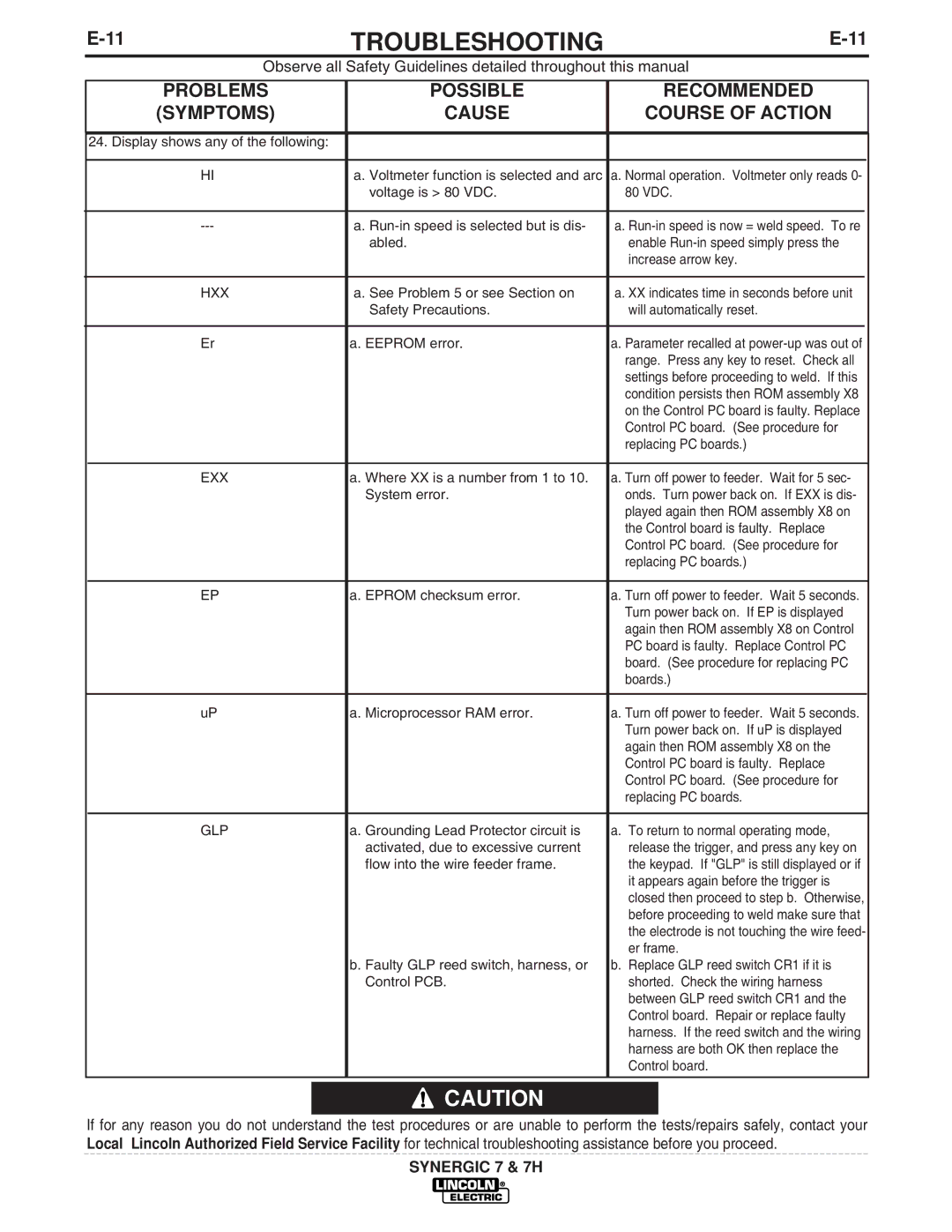
24. Display shows any of the following: |
|
|
|
|
|
| |
HI | a. Voltmeter function is selected and arc | a. Normal operation. Voltmeter only reads 0- | |
| voltage is > 80 VDC. | 80 VDC. | |
|
|
|
|
a. | a. | ||
| abled. | enable | |
|
| increase arrow key. | |
|
|
|
|
HXX | a. See Problem 5 or see Section on | a. XX indicates time in seconds before unit | |
| Safety Precautions. | will automatically reset. | |
|
|
|
|
Er | a. EEPROM error. | a. Parameter recalled at | |
|
| range. Press any key to reset. Check all | |
|
| settings before proceeding to weld. If this | |
|
| condition persists then ROM assembly X8 | |
|
| on the Control PC board is faulty. Replace | |
|
| Control PC board. (See procedure for | |
|
| replacing PC boards.) | |
|
|
| |
EXX | a. Where XX is a number from 1 to 10. | a. Turn off power to feeder. Wait for 5 sec- | |
| System error. | onds. Turn power back on. If EXX is dis- | |
|
| played again then ROM assembly X8 on | |
|
| the Control board is faulty. Replace | |
|
| Control PC board. (See procedure for | |
|
| replacing PC boards.) | |
|
|
| |
EP | a. EPROM checksum error. | a. Turn off power to feeder. Wait 5 seconds. | |
|
| Turn power back on. If EP is displayed | |
|
| again then ROM assembly X8 on Control | |
|
| PC board is faulty. Replace Control PC | |
|
| board. (See procedure for replacing PC | |
|
| boards.) | |
|
|
| |
uP | a. Microprocessor RAM error. | a. Turn off power to feeder. Wait 5 seconds. | |
|
| Turn power back on. If uP is displayed | |
|
| again then ROM assembly X8 on the | |
|
| Control PC board is faulty. Replace | |
|
| Control PC board. (See procedure for | |
|
| replacing PC boards. | |
|
|
| |
GLP | a. Grounding Lead Protector circuit is | a. To return to normal operating mode, | |
| activated, due to excessive current | release the trigger, and press any key on | |
| flow into the wire feeder frame. | the keypad. If "GLP" is still displayed or if | |
|
| it appears again before the trigger is | |
|
| closed then proceed to step b. Otherwise, | |
|
| before proceeding to weld make sure that | |
|
| the electrode is not touching the wire feed- | |
|
| er frame. | |
| b. Faulty GLP reed switch, harness, or | b. Replace GLP reed switch CR1 if it is | |
| Control PCB. | shorted. Check the wiring harness | |
|
| between GLP reed switch CR1 and the | |
|
| Control board. Repair or replace faulty | |
|
| harness. If the reed switch and the wiring | |
|
| harness are both OK then replace the | |
|
| Control board. | |
|
|
|
|
![]() CAUTION
CAUTION
If for any reason you do not understand the test procedures or are unable to perform the tests/repairs safely, contact your Local Lincoln Authorized Field Service Facility for technical troubleshooting assistance before you proceed.
SYNERGIC 7 & 7H
