Chapter 3
Chapter 3:
Installation
Overview
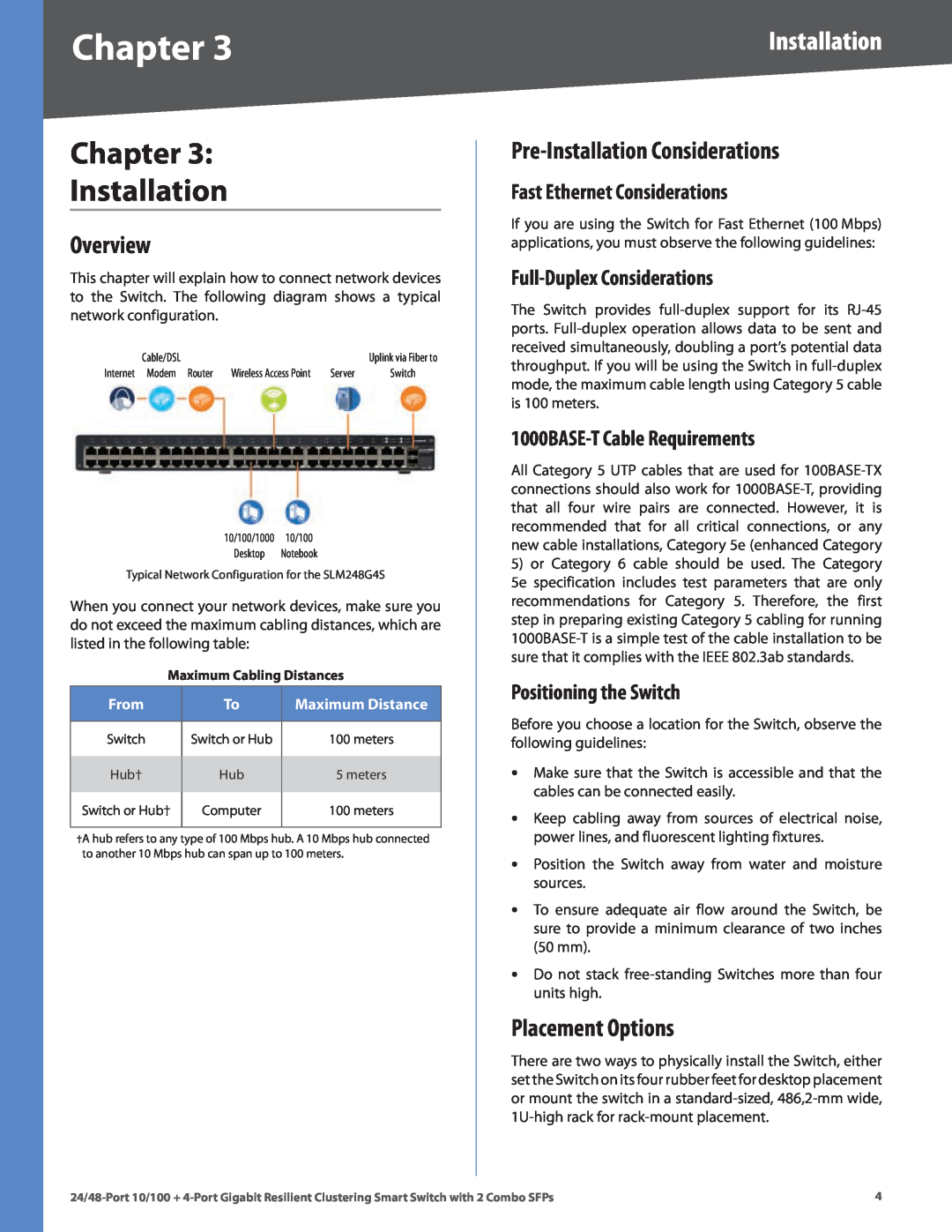
This chapter will explain how to connect network devices to the Switch. The following diagram shows a typical network configuration.
Cable/DSL |
|
| Uplink via Fiber to |
Internet Modem Router | Wireless Access Point | Server | Switch |
10/100/1000 10/100 Desktop Notebook
Typical Network Configuration for the SLM248G4S
When you connect your network devices, make sure you do not exceed the maximum cabling distances, which are listed in the following table:
Maximum Cabling Distances
From | To | Maximum Distance |
|
|
|
Switch | Switch or Hub | 100 meters |
Hub† | Hub | 5 meters |
Switch or Hub† | Computer | 100 meters |
|
|
|
†A hub refers to any type of 100 Mbps hub. A 10 Mbps hub connected to another 10 Mbps hub can span up to 100 meters.
Installation
Pre-Installation Considerations
Fast Ethernet Considerations
If you are using the Switch for Fast Ethernet (100 Mbps) applications, you must observe the following guidelines:
Full-Duplex Considerations
The Switch provides
1000BASE-T Cable Requirements
All Category 5 UTP cables that are used for
5)or Category 6 cable should be used. The Category
5e specification includes test parameters that are only recommendations for Category 5. Therefore, the first step in preparing existing Category 5 cabling for running
Positioning the Switch
Before you choose a location for the Switch, observe the following guidelines:
•Make sure that the Switch is accessible and that the cables can be connected easily.
•Keep cabling away from sources of electrical noise, power lines, and fluorescent lighting fixtures.
•Position the Switch away from water and moisture sources.
•To ensure adequate air flow around the Switch, be sure to provide a minimum clearance of two inches (50 mm).
•Do not stack
Placement Options
There are two ways to physically install the Switch, either set the Switch on its four rubber feet for desktop placement or mount the switch in a