CF-Y5
For U.K This apparatus must be earthed for your safety
How to replace the fuse
Laser Safety Information
Page
Page
Contents
„ Main Specifications
Specifications
Secondary cache memory
Bluetooth
Wireless LAN
Useful Information Getting Started
Names and Functions of Parts
Headphone Jack
SD Memory Card Slot Bluetooth Antenna
Battery Latches Battery Pack Emergency Hole RAM Module Slot
DC-IN Jack Ventilation Hole External Display Port
Yonah LV Dual Core
Block Diagram
Diagnosis Procedure
Flow Chart
Troubleshooting
Diagnosis
Power-On Self Test Boot Check
Error Diagnosis by Checking Beep Signal Sound
Outline of Post
Stuck key
02D0 System cache error Cache disabled
Shift and left Shift keys
When you execute an automatic test
When you execute the enhancing test
Self Diagnosis Test
Operation of PC-Diagnostic Utility
Content of the setup is returned to the setting of the user
PC-Diagnostic utility End method
Selection of tested device
Place with possibili
Enhancing
Memory as Vram may fail with
Cable characteristic and device
Standard Enhanced
Breakdown. e.g.. Head, Motor
LCD
Wiring Connection Diagram
Disassembly instructions
Removing the Keyboard
Before disassembly, be sure to perform the following steps
Preparation
Removing the HDD
Preparation perform the .2.1., 9.2.3. first
Removing the Top Case
SUB DVD
Removing the SUB DVD
Preparation perform the .2.1., 9.2.3. and 9.2.4. first
Ffcpadffcsw
Top Case Screw Q Solenoid Line Hold Sheet Cable Fixed Sheet
Removing the Touch Pad / LCD Knob
Removing the Solenoid / Disc Cover Lock
Pad WP Sheet LCD Knob LCD Latch Spring Top Case
FAN
Removing the Speaker L, R
Removing the FAN
Preparation perform the .2.1 9.2.4. first
Removing the Main Board
Removing the Drive Unit
Gadket
Removing the Antenna Board Unit L, R
Removing the DC-IN Cable
USB FPC
Preparation perform the .2.1 9.2.11. first
Removing the Modem
Modem
Preparation perform the .2.1 9.2.18. first
Removing the LCD Unit
Removing the Hinge Cover L, R
Removing the LCD Unit and the LCD Rear
CN2
Removing the LCD Cable / Inverter Board
2mm Hinge Side 1mm Hook Side LCD Side Cushion
Assembly knowhow of the LCD
Assembly of the LCD Front
Putting LCD Side Cushion / LCD Tape
Rib Rib standard
Putting LCD Side Rubber / LCD Side Damper
LCD
Side Rubber
Putting LCD Magnet
Putting LCD Cushion / Assembly of the Inverter
Externals match
Putting Tape for LCD Cable
Preparation for Inverter Case
Order
Page
Page
Putting Line Hold Sheet / Antenna Sheet / BT PWB Cushion
Assembly knowhow of the Main Board
Putting MCH Sheet / Heat Spreader Bottom
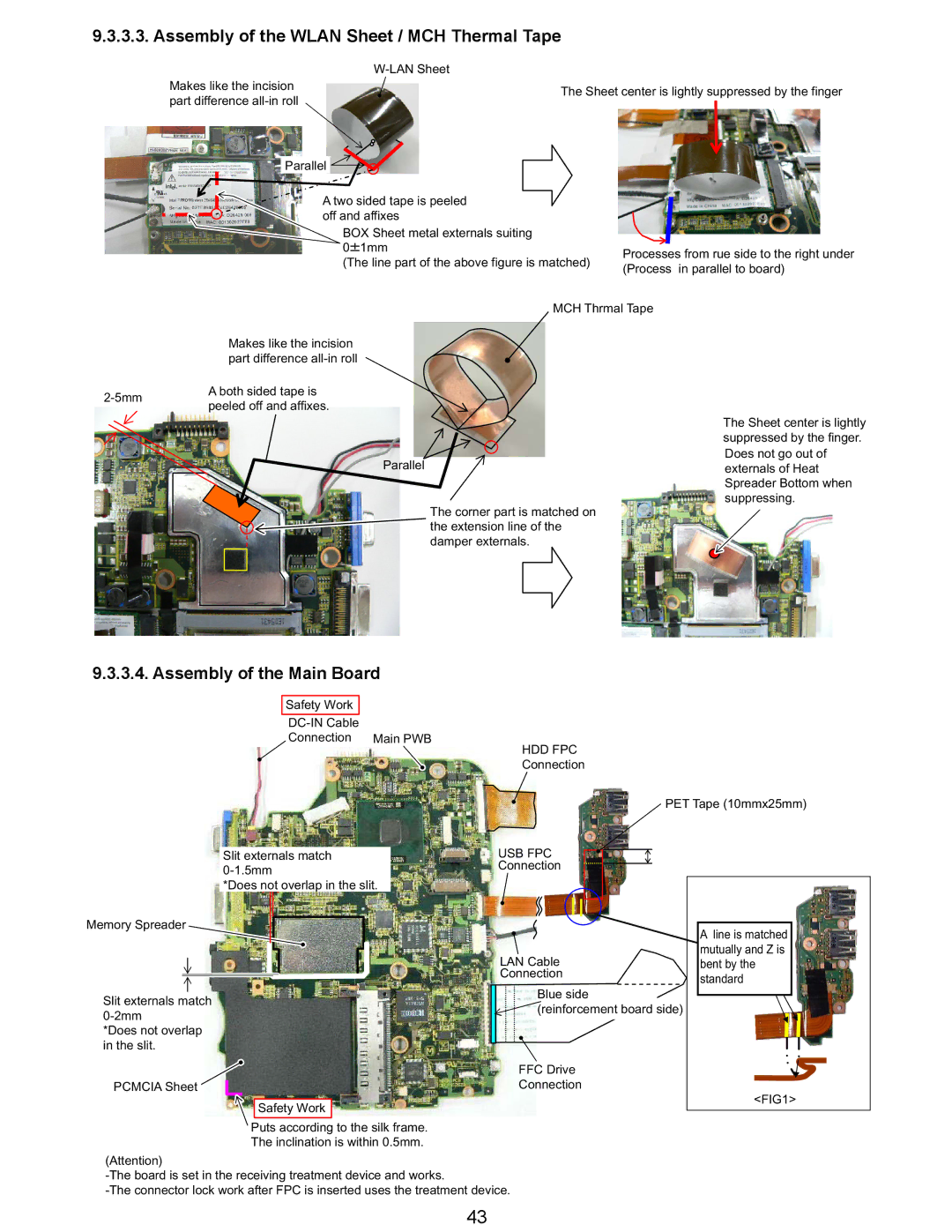
Assembly of the Main Board
Assembly of the Wlan Sheet / MCH Thermal Tape
HDD FPC
Right before building Left before building Square hole
Assembly of the Card Bus Ejector
Safety work
Assembly of the Wireless LAN Module / Modem
DXQT2+E6FNL
Insert the Main Board
DXQT2+D25FNL
Assembly of the Disk Cover
Assembly knowhow of the Top Case
LAN on /OFF
Assembly of the Top Case
Lan Sw Blank Installation
Putting Disk Angle Cushion
SEC
Assembly of the LCD Knob / Putting Cushion
Top Case Rib
Case rib and folds to the rib side
Pad Cover Externals
Assembly of the Touch Pad
Install the Pad Cover
Safety work
Pad Cover installation position
Cushion
Putting Sheet
Fixation seat
Affixes Disk cover cushion
Assembly of the Break Lever
Axis nor the shuttlecock
Assembly of the FAN
Conclusion
Confirmation two places as
Assembly of the Disk Cover Click
Assembly of the Disk Cover Lock / SW PCB
Engagement fingernail is
Possible to recycle
SW PCB yellow line Screw DXHM0056ZA Yellow line
SW PCB
Affixation Disk Lever Fix Cushion
Assembly of the Speaker
Assembly of the Solenoid
Wiring Speaker Cable
Difference line
Putting Cushion / Tape / Sheet
Assembly of the SW PCB FFC
Page
Assembly of the Dimm Cover
Assembly knowhow of the Bottom Case
Putting Line Hold Sheet
LED Lenz SD
Cutting lack part top side
Putting Foot Rubber
FIG1 Safety Work
Do not go out of the rib
Main PWB Assy
Assembly knowhow of the Body
Installation of Main Board
Keyboard preparation
FIG2
Assembly of the HDD Slot Guard
Insert the Modem Cable in the slit
Putting Line Hold Sheet 3 / Line Hold Cushion
Back
Side without tape
FFC
ANT PWB
Cable black Tape Externals
Installation of LCD Unit
Side with I-PEX stamp
Cable in CN
CPU
DFHE5035ZB
Affixes Gasket Cloth FIG1
Assembly of the DVD Drive
Assembly of the Body
Installation of Power Knob / LAN SW Knob
LAN ON/OFF
Top Case side screw tightening
Installation of K/B Heat Spreader
DXQT2+E6FNL DXQT2+F3FNL DXQT2+E10FNL DRQT2+E8FKL
Installation of Keyboard
Installation of Disk Cover / Disk Side Cover
Side Cover L
Installation of K/B Side Cover
How to detach Keyboard and K/B Side Cover
Side Cover R
Bottom Case side screw tightening
Installation of HDD
DFQT0046ZA
Putting Label
Screw tightening torque
Exploded View
K52 K145 K157
Cabinet Section
N7 Screw tightening torque
REF. no and Area
Replacement Parts List
DFHG1874YA LCD Cushion
DFMD1202ZA DC Jack Plate
DFHR3D21YA Line Hold Sheet
DXQT2+E6FNL Screw
EEFSX0D331ER
CF-Y5LWVYZBM 2006/11/16 REF. no and Area
EEFCX0D221R
EEFCD0D101ER
Connector
EEFCX0J101R
EEFCX0G151R
DEDRB081L20 Diode
IC, Temperature Censor IC
IC, USB Power SW
Diode
IC, Power Management Switch
IC, FET Switch
IC, Q-SWITCH
IC, Audio Power Amplifier
ERJ2GEJ102X RESISTOR, 1/16W, 1KΩ
B1GFCFEN0003 Transistor
B1GBCFNN0042 Transistor
B1GBCFNL0017 Transistor
ERJ2GE0R00X RESISTOR, 1/16W, 0Ω
ERJ2GEJ103X RESISTOR, 1/16W, 10KΩ
ERJ2GEJ201X
ERJ2GEJ100X
ERJ2GEJ472X
ERJ2GEJ105X RESISTOR, 1/16W, 1MΩ
ERJ2RKF3922X
ERJ2RKF2002X RESISTOR, 1/16W, 20KΩ
Bluetooth Module
Slide Switch
EVQPLDA15 Switch
CONNECTOR, USB
ERJ2GE0R00X RESISTOR, 1/16W, 0Ω