Maxtor Atlas 10K Product Manual
UL/CSA/VDE/TUV
Before You Begin
Regulatory Statements
Table of Contents
Specifications
Page
Feature Descriptions
Negotiated Rate Information page Reference
List of Figures
List of Tables
Command Support Data Page Command or Operation Codes
Persistent Reservation in Command Descriptor
114 Persistent Reservation OUT Command Descriptor
106
136
About this Manual
Audience Manual Organization
Terminology and Conventions
Asic
Mode Select
References
KEY Features
Product Overview
Maxtor Atlas 10K
Reliability
Regulatory Compliance Standards
Hardware Requirements
Product EMI/EMC Qualifications
Handling
SAFETY, HANDLING, & Electrostatic Discharge Protection
Safety Precautions
Electrostatic Discharge ESD Protection
Shows The Mechanical Dimensions of the drives
Space Requirements
Shock Feet
Unpacking Instructions
2Drive Packing Assembly
Jumper Options on the 68-Pin Wide PCB
Configuration Jumpers and Connections
Hardware Options
Pin Power Connector Pin Option Pin Scsi
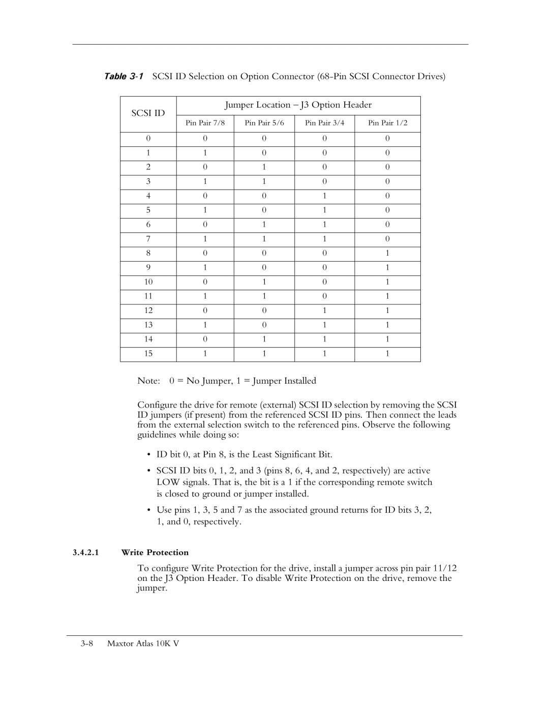
Scsi ID
Maxtor Atlas 10K V drives have three Spin Up modes
SCA-2 80-Pin Connector Versions
4Pin Locations on SCA-2 Connector
Location on SCA Connector
Staggerspin Delayspin
Interface Connector J1
Shows the various connector styles
Maxtor Atlas 10K V
1 68-Pin Wide Scsi Connector LVD
Signal Name Connector Contact Number Cable Conductor
580-Pin SCA-2 LVD Pin Assignments
2 80-Pin SCA-2 Scsi Connector LVD
PIN Connector Contact Signal Name Cable Conductor Number
2.1 80-Pin SCA-2 Mating Connectors
3 68-Pin Wide Single-Ended Scsi Connector
668-Pin Wide Single-Ended Pin Assignments
4 80-Pin SCA-2 Single-Ended Scsi Connector
Drive Mounting and Installation
Orientation
Mounting Screw Clearance
7Mounting Screw Clearance for Maxtor Atlas 10K V Drive
Mounting
Ventilation
9Crosswise Airflow Cooling
Specifications
Specification Summary
Scsi ‘Hard’ Reset Time6 Ms typical
Formatted Capacity
Timing Specifications
Data Transfer Rates
Power Reset Limits
Power
Power Sequencing
Drive Power Dissipation
Operation
Acoustics
Acoustic Toned Quality
Mechanical
Environmental Conditions
Electromagnetic Conditions
1 EMI/RFI Susceptibility
2 ESD
Sensitivity to Magnetic Fields
Reliability
Disk Errors
9Error Rates
Overview of the Scsi Command Descriptions
Receive Diagnostic Results
Send Diagnostic
Persistent Reservation OUT
Read Buffer
Page
Command Descriptor Block
Bit Byte
Description
MSB
Field Description
Indicate the number of sectors to be transferred
Naca
Status Definition Meaning
Status/Error Reporting
Linked Commands
Page
Data Transfer Command Components
8DATA-Phase Command Contents
Diagnostic
Read Defect
Reassign
Blocks Receive
Scsi Command Descriptions
Common Fields
10CHANGE DEFINITION-Field Descriptions
9CHANGE Definition Command Descriptor Block-Data Format
Change Operating Definition 40h
Format Unit Command 04h
11FORMAT Unit Command Descriptor Block-Data Format
12FORMAT Unit Command-Field Descriptions
Five Forms of Format Unit Commands
13FORMAT Unit Command Supported Options
Format Unit Parameter List
14FORMAT Unit Parameter List-Data Format
15 .FORMAT Unit Defect List Header-Data Format
16FORMAT Unit Defect List Header-Field Descriptions
FOV Dpry
DSP
17FORMAT Unit Defect Descriptor-Block Format
19FORMAT Unit Initialization Pattern Descriptor-Data Format
Initialization Pattern Type Description
21FORMAT Unit Initialization Pattern Type
Name Description
Inquiry Command 12h
22INQUIRY Command Descriptor Block-Data Format
23 Inquiry Command Descriptor Block-Field Descriptions
Evpd
Byte Bit
Standard Inquiry Data
24Standard Inquiry Data Page-Data Format
QAS
25Standard Inquiry Data Page-Field Descriptions
Field Name Value Description
Vital Product Data Pages
26Supported Vital Product Data Pages -Data Format
27Vital Product Data-Page Codes
28Unit Serial Number Page-Data Format
30Implemented Operating Definition Page-Data Format
31Implemented Operating Definition Page-Field Descriptions
32ASCII Implemented Operating Definition Page Data Format
33Device Identification Page Data Format
LSB
35Command Support Data Page-Data Format
34Device Identification Page Field Description
36Command Support Data Page-Field Descriptions
37Command Support Data Page Command or Operation Codes
Hex Data Returned When Inquiry is Received and CmdDt Bit
OpCode Command Support
Version Length
RES. OUT
Persist
RES.
LOG Select Command 4Ch
38LOG Select Command Descriptor Block-Data Format
39LOG Select Command Descriptor Block-Field Descriptions
PCR
Code Description
LOG Sense Command 4Dh
40 Disk Drive Log Pages
LOG Sense Command Descriptor Block
41LOG Sense Command Descriptor Block-Data Format
42LOG Sense Command Descriptor Block-Field Descriptions
Reset
LOG Sense Log Pages
43LOG Sense Log Page Format-Data Format
TSD ETC
Lbin
46Generic Log Parameter-Field Descriptions
Mode Select 6 Command 15h
Initiator-Changeable Mode Pages
47MODE Select 6 Command Descriptor Block-Data Format
48MODE Select 6 Command Field Descriptions
49Initiator-Changeable Mode Pages
Code Name Function Size Bytes
Mode Page Types
Mode Parameter List
50 Mode Page Types
51Mode Parameter List-Data Format
52Mode Parameter List-Field Descriptions
53Mode Parameter Header 6-Byte-Data Format
54Mode Parameter Header- Field Descriptions
55Mode Parameter Block Descriptor-Data Format
56 Mode Parameter Block Descriptor-Field Descriptions
Categories of Changeable Pages
Unit Attention Condition Page 00h
57Categories of Changeable Pages
Read-Write Error Recovery Page 01h
60Read-Write Error Recovery Page-Page
Field Default Value Description
59Unit Attention Condition
Awre
61Read-Write Error Recovery Page Field Descriptions
Default Description
Field Default Description
63 Disconnect-Reconnect-Field Descriptions
Disconnect-Reconnect Page 02h
62Disconnect-Reconnect
EER PER
Verify Error Recovery Page 07h
64Verify Error Recovery Page-Page
66Caching Page-Page
65Verify Error Recovery Page-Field Descriptions
Caching Page 08h
67Caching Page Field Descriptions
WCE
Control Mode Page 0Ah
68Control Mode Page Data Format Page 0Ah
FSW
Gltsd Rlec
Eeca RAC
SWP Raerp Uaaer Eaerp
Eeca
69Control Mode Page-Field Descriptions
Gltsd
Maxtor Atlas 10K
LPN
Notch and Partition Page 0Ch
70Notch and Partition Page-Page 0Ch
71Notch and Partition Page-Field Descriptions
Port Control Mode Page 19h
72Port Control Page Short Format
73Port Control Page Long Format
74Margin Control Subpage 01h
75 Field Descriptions
Maxtor Atlas 10K
76Saved Training Configuration Subpage 02h
77Negotiated Settings Subpage 03h
78 Transceiver Period Factor
Code Transceiver Period Factor
Sent Received
79Transceiver Mode
Code Transceiver Mode
Bit Name Description
80Report Transfer Capabilities Subpage
81 Field Descriptions
Information Exceptions Control Page 1Ch
82Information Exceptions Control Page-Page 1Ch
Ewasc
Mrie MSB
Perf
84Codes Used by the Mrie Field
Mode Select 10 Command 55h
85MODE Select 10 Command Descriptor Block-Data Format
86Mode Parameter Header 10-Byte-Data Format
87Mode Parameter Block Descriptor-Data Format
88Mode Parameter Block Descriptor-Field Descriptions
Mode Sense 6 Command 1Ah
89MODE Sense 6 Command Descriptor Block-Data Format
90MODE Sense Command-Field Descriptions
91Mode Parameter Header 6 Byte-Data Format
Read-Only Mode Pages
93Read-Only Mode Pages
Format Device Page 03h
94Format Device Page-Page
Maxtor Atlas 10K
95Format Device Page-Field Descriptions
Ssec
RPL
Rigid Disk Geometry Page 04h
96Rigid Disk Geometry Page-Page
97Rigid Disk Geometry Page-Field Descriptions
Tion
Mode Sense 10 Command 5Ah
98MODE Sense 10 Command Descriptor Block-Data Format
99Mode Parameter Header 10 Byte-Data Format
100Mode Parameter Block Descriptor-Data Format
Bit 7 This bit is set if the drive is write protected
Persistent Reservation in Command 5Eh
103PERSISTENT Reservation in Command-Field Descriptions
104Read Keys Parameters-Data Format
Described in -106 and -107 respectively
107Read Reservations Parameters-Field Descriptions
Data Description Field
110Persistent Reservation Type Codes and Their Meanings
Code Name Description
Exclusive
LU EX
Persistent Reservation Already Held
Read Write
Persistent Reservation OUT Command 5Fh
113PERSISTENT Reservation OUT Command-Field Descriptions
Tion OUT
Powering down the logical unit, if the last
Tions Preempted
Pre-empting initiator
Clear portion of the action executes normally
115Persistent Reservation Type Codes and Their Meanings
116PERSISTENT Reservation OUT Parameter List-Data Format
Registrants
Extent Length
Nored for all other types of service actions
Eter List
118Device Server Interpretation of Service and Scope Value
Parameters
120READ 6 Command-Field Descriptions
Read 6 Command 08h
119READ 6 Command-Data Format
122 Read 10 Command-Field Descriptions
Read 10 Command 28h
121READ 10 Command-Data Format
Read Buffer Command 3Ch
123READ Buffer Command-Data Format
124READ Buffer Command-Field Descriptions
Buffer Offset must be
Read Capacity Command 25h
125READ Capacity Command-Data Format
126READ Capacity Command-Field Descriptions
127READ Capacity Returned Data-Data Format
Read Defect Data Command 10 37h
128READ Defect Data 10 Command-Data Format
129READ Defect Data 10 Command-Field Description
130Defect Descriptor-Block Format
132Defect List Header -Data Format
133Defect List Header-Field Descriptions
135 Read Defect Data 12 Command-Field Description
Read Defect Data Command 12 B7h
134READ Defect Data 12 Command-Data Format
139Defect List Header-Field Descriptions
136Defect Descriptor-Block Format
138Defect List Header-Data Format
Read Long Command 3Eh
140READ Long Command Descriptor Block-Data Format
141READ Long Command Descriptor Block-Field Descriptions
142READ Long Command-Returned Data
144READ Skip Mask Command-Field Description
Read Skip Mask Command E8h
143READ Skip Mask Command-Data Format
Reassign Blocks Command 07h
145REASSIGN Blocks Command Descriptor Block-Data Format
146REASSIGN Blocks Defect List Header-Data Format
147REASSIGN Blocks Defect List Header -Field Description
Maxtor Atlas 10K 105
Receive Diagnostic Results Command 1Ch
149Diagnostic Pages Supported by The Drives
Description Size In Bytes Code
PCV
Translate Address Page 40h
Supported Diagnostics Pages Page 00h
152Supported Diagnostics Pages Page-Data Format
153Translate Address Page-Data Format
154Translate Address Page-Field Descriptions
156RELEASE 6 Command -Field Descriptions
Release 6 Command 17h
155RELEASE 6 Command Descriptor Block-Data Format
158 Release 10 Command Field Descriptions
Release 10 Command 57h
157RELEASE 10 Command Descriptor Block-Data Format
Report Device Identifier Command A3h
161REPORT Device Identifier Parameter List-Data Format
Maxtor Atlas 10K
Report Luns Command A0h
163REPORT Luns Command Descriptor Block-Data Format
164REPORT Luns Command Descriptor Block-Field Description
165LUN Reporting Parameter List -Data Format
Request Sense Command 03h
166REQUEST Sense Command Descriptor Block-Data Format
167REQUEST Sense Command Descriptor Block-Field Description
Sense Data Availability
Sense Data Format for Error Code 70h and Error Code 71h
168Sense Data Format for Error Code 70h or 71h-Data Format
Status Reporting
EOM ILI
169Sense Data Fields Error Code 70h-Field Descriptions
FRU
170Supported Sense Keys
Sense Key Code Description
171Sense Key Information Field Contents
Sense Meaning Key Code
EC REC SVO Missed STM
Sense Meaning Key Code
Maxtor Atlas 10K 121
Sense Meaning Key Code
Maxtor Atlas 10K 123
Sense Meaning Key Code
Maxtor Atlas 10K 125
Sense Meaning Key Code Qualifier
Maxtor Atlas 10K 127
Init
Maxtor Atlas 10K 129
Sense Meaning Key Code
Maxtor Atlas 10K 131
173 Sense-Key Specific Field Contents
174ILLEGAL Request Sense Key Field Pointer Bytes\Data Format
179MEDIUM Error or Recovered Error Sense Key Retry Count
BPV
Field Descriptions
181 Reserve 6 Command-Field Descriptions
Reserve 6 Command 16h
180RESERVE 6 Command Descriptor Block-Data Format
183 Reserve 10 Command-Field Descriptions
Reserve 10 Command 56h
182RESERVE 10 Command Descriptor Block-Data Format
184Extent Descriptors-Data Format
185Reservation Types
187RESERVE 10 ID Only Parameter List-Data Format
Reservation Type Description
Rezero Unit Command 01h
188REZERO Unit Command Descriptor Block-Data Format
Seek 6 Command 0Bh
189SEEK 6 Command Descriptor Block-Data Format
Seek 10 Command 2Bh
190SEEK 10 Command Descriptor Block-Data Format
192 Send Diagnostic Command-Field Descriptions
Send Diagnostic Command 1Dh
191SEND Diagnostic Command Descriptor Block-Data Format
Supported Diagnostic Page List
193Supported Diagnostic Page List-Data Format
Translate Address
194Translate Address Page-Data Format
198SET Device Identifier Parameter List-Field Descriptions
SET Device Identifier Command A4h
197SET Device Identifier Parameter List-Data Format
200START Stop Unit Command-Field Descriptions
Start Stop Unit Command 1Bh
199START Stop Unit Command Descriptor Block-Data Format
202SYNCHRONIZE Cache Command-Field Descriptions
Synchronize Cache Command 35h
201SYNCHRONIZE Cache Command Descriptor Block-Data Format
Test Unit Ready Command 00h
203TEST Unit Ready Command Descriptor Block-Data Format
205 Verify Command-Field Descriptions
Verify Command 2Fh
204VERIFY Command Descriptor Block-Data Format
207 Write 6 Command-Field Descriptions
Write 6 Command 0Ah
206WRITE 6 Command Descriptor Block-Data Format
209 Write 10 Command-Field Descriptions
Write 10 Command 2Ah
208WRITE 10 Command Descriptor Block-Data Format
211WRITE and Verify Command-Field Descriptions
Write and Verify Command 2Eh
210WRITE and Verify Command Descriptor Block-Data Format
Write Buffer Command 3Bh
212WRITE Buffer Command Descriptor Block-Data Format
213WRITE Buffer Command-Field Descriptions
Write Long Command 3Fh
Write Same Command
214WRITE Long Command Descriptor Block-Data Format
215WRITE Long Command-Field Descriptions
217WRITE Same Field Description
216WRITE Same Command Descriptor Block-Data Format
218WRITE Skip Mask Command EAh
219WRITE Skip Mask Command Field Description
Maxtor Atlas 10K
Feature Descriptions
WRITE-BACK Caching
Average Access Time
Zero Latency READ/WRITE
DISCONNECT-RECONNECT
Track and Cylinder Skewing
Media Error Protection
Transfer Error Protection
Addressing Error Protection
Data Sector Reallocation Error Protection
Tagged Command Queuing
Command Reordering
Data Verification
Banded Recording
Periodic Self-Adjustments
Diagnostics
Power On Self Test Post
Error Recovery
Maxtor Atlas 10K
Diffsens Switching
Diffsens
DT and ST Clocking
1ST and DT CLocking
Adaptive Active Filter AAF
Cyclic Redundancy Checking
Domain Validation
Transmitter Pre-Compensation with Cutback
Free Running Clock FRC
Skew Compensation
Information Unit Transfers
System Considerations
Applicable Scsi Physical Documents
Quick Reference
Table A-1SCSI-2/SCSI-3 Equivalent Terminology
Scsi Commands and Messages
Table A-2SCSI-3 Quick Reference Commands
Table A-3SCSI-3 Quick Reference Messages
Table A-4SCSI-3 Quick Reference Pages
Maxtor Atlas 10K
Table A-5SCSI-3 Quick Reference Sense Keys
Table A-6SCSI-3 Quick Reference Status Codes
Table B-1Transfer Period Factor Field Values When Parl =
Appendix B Negotiated Rate Information page Reference
Table B-2Transfer Period Factor Field Values When Parl =
Settings for the QAS, DT, and IU fields
Command
Glossary
Glossary
Maxtor Atlas 10K V G-3
4Maxtor Atlas 10K
Maxtor Atlas 10K V G-5
LOW-VOLTAGE Differential LVD
Maxtor Atlas 10K V G-7
8Maxtor Atlas 10K
Maxtor Atlas 10K V G-9
10Maxtor Atlas 10K
True Refers to the logical-one or
12Maxtor Atlas 10K
Index
17,5-21
Parameter List 5-11,5-12,5-17,5-18, 5- 37, 5-39,5-130,5-141
107, 5-108,5-132
141