Disassembly Procedures
!WARNING
To avoid risk of electrical shock, personal injury or death; disconnect power to unit before servicing.
Gas Valve
1.Disconnect power supply to unit
2.Remove Front Panel.
3.Shut off gas supply and disconnect supply line to valve.
4.Disconnect wire harness at valve coils.
5.Disconnect wires from radiant sensor.
6.Loosen brass nut attaching angle connector to gas valve.
7.Remove two screws holding valve and burner assembly to base.
8.Slide valve bracket out of slot in base and remove valve and burner assembly.
9.Remove two screws holding gas valve to bracket on underside.
Combustion Cone
1.Disconnect power supply to unit.
2.Remove Front Panel.
3.Remove burner and igniter. Be careful igniter is fragile.
4.Remove wires from
5.Remove screw in front of cone holding it to base.
6.Remove screw at back of combustion cone holding cone tab to inlet duct.
7.Pull combustion cone out of dryer.
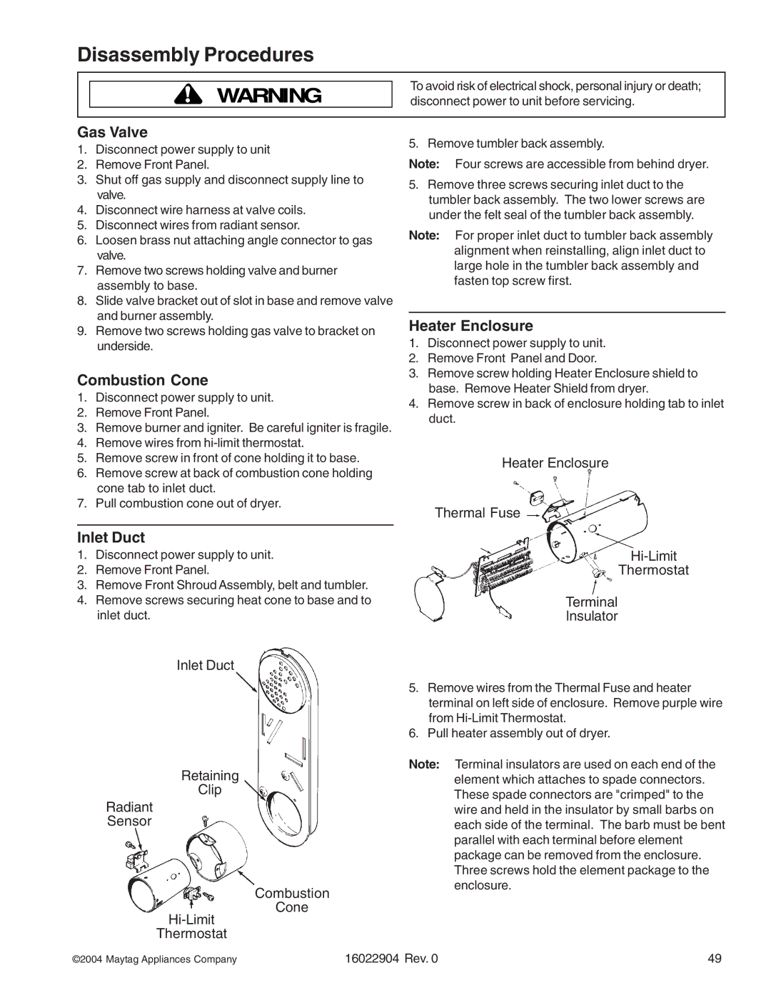
Inlet Duct
1.Disconnect power supply to unit.
2.Remove Front Panel.
3.Remove Front Shroud Assembly, belt and tumbler.
4.Remove screws securing heat cone to base and to inlet duct.
Inlet Duct
Retaining
Clip
Radiant
Sensor
Combustion
Cone
Thermostat
5. Remove tumbler back assembly.
Note: Four screws are accessible from behind dryer.
5.Remove three screws securing inlet duct to the tumbler back assembly. The two lower screws are under the felt seal of the tumbler back assembly.
Note: For proper inlet duct to tumbler back assembly alignment when reinstalling, align inlet duct to large hole in the tumbler back assembly and fasten top screw first.
Heater Enclosure
1.Disconnect power supply to unit.
2.Remove Front Panel and Door.
3.Remove screw holding Heater Enclosure shield to base. Remove Heater Shield from dryer.
4.Remove screw in back of enclosure holding tab to inlet duct.
Heater Enclosure
Thermal Fuse
Thermostat
Terminal
Insulator
5.Remove wires from the Thermal Fuse and heater terminal on left side of enclosure. Remove purple wire from
6.Pull heater assembly out of dryer.
Note: Terminal insulators are used on each end of the element which attaches to spade connectors. These spade connectors are "crimped" to the wire and held in the insulator by small barbs on each side of the terminal. The barb must be bent parallel with each terminal before element package can be removed from the enclosure. Three screws hold the element package to the enclosure.
©2004 Maytag Appliances Company | 16022904 Rev. 0 | 49 |