Troubleshooting Procedures
!WARNING
To avoid risk of electrical shock, personal injury or death, disconnect power to unit before servicing, unless testing requires power.
ELECTRICAL TROUBLESHOOTING
The malfunction of an electrical circuit cannot easily be diagnosed unless you first understand how it functions when operating normally. The electrical schematic and wiring diagram includes a cycle sequence chart keyed to the contacts in the timer, relay and/or control switches.
!CAUTION
Resistance or continuity testing is done with the product disconnected from power. Failure to do so can result in damage to your meter.
For the most part, we will only be concerned with continuity. Is there a path or not? References are made between a “closed” (Continuity) reading and an “open (No continuity) reading. One note, when you get and “open” reading, try a higher resistance range (setting). A very high resistance appears as an “open” on the lower ranges. For best accuracy always “rezero” meter when changing ranges and/or the physical position of the meter.
Continuity testing, as related to an electrical component, is the check of a part for an “open” or closed” circuit.
Continuity test of load devices will show varying levels of resistance from very low for some transformer and motor windings to very high for some timer motors and components on control boards. Usually it is more important to know if there is a path for current flow through a device (continuity ) that to know the exact resistance (ohms) of the device.
Continuity tests of switches will show virtually no resistance across a closed contacts. Resistance, even low value indicate burned or dirty contacts in a switch.
When checking components or circuit paths for continuity, external wiring should be disconnected to eliminate false readings through external paths. Isolate what you want to test.
Drive Motor Check
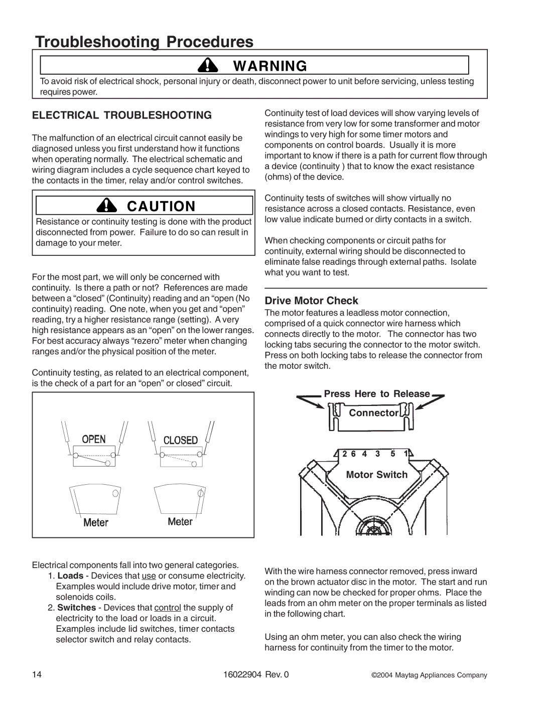
The motor features a leadless motor connection, comprised of a quick connector wire harness which connects directly to the motor. The connector has two locking tabs securing the connector to the motor switch. Press on both locking tabs to release the connector from the motor switch.
Press Here to Release
Connector
Motor Switch
Electrical components fall into two general categories.
1.Loads - Devices that use or consume electricity. Examples would include drive motor, timer and solenoids coils.
2.Switches - Devices that control the supply of electricity to the load or loads in a circuit. Examples include lid switches, timer contacts selector switch and relay contacts.
With the wire harness connector removed, press inward on the brown actuator disc in the motor. The start and run winding can now be checked for proper ohms. Place the leads from an ohm meter on the proper terminals as listed in the following chart.
Using an ohm meter, you can also check the wiring harness for continuity from the timer to the motor.
14 | 16022904 Rev. 0 | ©2004 Maytag Appliances Company |